전계방출 전기추진 추력기 연구개발 현황
Copyright Ⓒ The Korean Society of Propulsion Engineers
This is an Open-Access article distributed under the terms of the Creative Commons Attribution Non-Commercial License(http://creativecommons.org/licenses/by-nc/3.0) which permits unrestricted non-commercial use, distribution, and reproduction in any medium, provided the original work is properly cited.
초록
뉴 스페이스 시대를 맞아 군집 초소형 위성의 활용이 전 세계적으로 증가함에 따라, 위성의 정밀 제어를 위한 추력기가 필수적으로 요구되고 있다. 전계방출 전기추진(Field Emission Electric Propulsion, FEEP) 추력기는 추진제로 액체 금속을 사용하는데, 강한 전기장에 의해 이온화된 액체 금속을 가속시키는 방식의 추력기이다. FEEP 추력기는 1 μN급에서 1 mN급까지의 추력 범위와 10,000 s 수준에 이르는 큰 비추력을 가지며, 구조가 단순하고 소형화가 가능하여 초소형 위성의 다양한 자세 및 궤도 제어 임무에 적합하다. 본 논문에서는 FEEP 추력기의 개요를 소개하고, 연구개발 현황에 대해서 살펴보고자 한다.
Abstract
As the application of nano-satellites constellation increases worldwide in the wake of New Space era, there is growing demand for the development of thrusters for precise attitude and orbit control of small satellites. Field Emission Electric Propulsion(FEEP) thruster uses a liquid metal as a propellant and accelerates the ionized liquid metal through a strong electric field at the tip of the metal surface. FEEP thruster technology is suitable for nano-satellites which require various missions for attitude and orbit control, because it provides thrust ranging from 1 μN to 1 mN with high specific impulse up to about 10,000 s and can be miniaturized due to its simple structure. In this paper, the basics of FEEP thrusters are introduced, then the current status of research and development of FEEP thrusters are presented.
Keywords:
Field Emission, Electric Propulsion, Electric Thruster키워드:
전계방출, 전기추진, 전기추력기1. 서 론
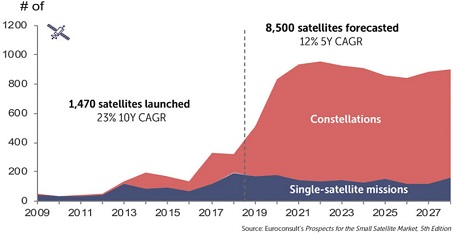
뉴 스페이스 시대를 맞아 군집 초소형 위성의 활용이 전 세계적으로 증가하고 있다. 우주 분야에 특화된 유럽의 컨설팅 기업 Euroconsult에 따르면(Fig. 1), 2009년에서 2018년까지 10년간 소형 위성 시장의 연평균 성장률은 23 %를 기록하였는데, 2019년부터 소형 위성 시장이 급격히 성장하고 있는 것으로 나타났다[1]. 또한, 2019년에서 2028년 사이 8,500대 이상의 소형 위성이 발사될 것으로 전망하였는데, 이 중에서 군집 운용 위성의 비율은 대략 80 %를 차지할 것으로 예측하였다[1]. 우주 공간에서 단독으로 운용 중인 저궤도 위성의 경우, 재방문 주기가 길어 지상국에서 원하는 영상을 획득하기까지 일정한 시간이 소요되기 때문에 위성을 활용한 다양한 서비스 수요에 신속하게 대응하지 못하는 한계가 있다. 그러나 초소형 위성을 군집으로 운용하면 위성의 재방문 주기를 대폭 줄일 수 있다.
초소형 위성을 군집 및 편대로 운용하는 다양한 프로그램이 증가하는 추세에서, 초소형 위성의 궤도유지 및 자세제어를 위한 추진시스템 탑재는 선택이 아닌 필수로 그 수요가 증가할 것으로 예상된다. 추력기를 사용하면 초소형 군집 위성의 신속한 궤도상 배치로 빠른 임무개시가 가능하고, 임무 종료 시 반통제 궤도이탈(semi-controlled deorbit)을 통해 우주 쓰레기 경감에도 기여할 수 있다.
기존의 화학식추력기와 비교했을 때, 전기추력기는 비추력이 높아 연료소모량이 낮으므로 장기간 임무를 수행하는 우주비행체의 주요 추진시스템으로 활용된다. 전기추력기는 추진제를 가속시키는 방식에 따라 전열(electrothermal)방식, 정전(electrostatic)방식, 전자기(electromagnetic)방식으로 분류할 수 있다[2,3]. 전열방식은 추진제를 전력으로 가열하여 고온의 가스로 만든 후 노즐을 통해서 팽창시켜 추력을 얻는다. 정전방식은 중성 상태의 추진제를 이온화시킨 후 전기장을 통해 추진제를 가속시키며, 전열방식과 달리 노즐을 통한 팽창 과정은 이루어지지 않는다. 전자기방식은 추진제 가스를 플라스마 상태까지 가열시킨 후 전자기력인 로런츠 힘으로 가속시킨다. 각각의 전기추진 방식과 이에 해당하는 사례를 Table 1에 정리하였다.
초소형 위성을 위한 추진시스템은 소형화 및 경량화가 관건이다. 현재 국내에서 개발된 화학식추력기 및 홀(Hall)추력기는 크기와 무게 측면에서 초소형 위성에 적합하지 않아 활용에 있어 제약이 존재하며 심지어는 거의 불가능하다. 또한, 일반적으로 홀추력기는 소형화시킬수록 효율이 낮아지는 경향을 보인다. 따라서 본 논문에서는 초소형 위성용 전기추력기의 대안 중 하나로 FEEP 추력기를 소개하고 이의 연구개발 동향에 대해 기술하고자 한다.
2. FEEP 추력기
2.1 작동 원리
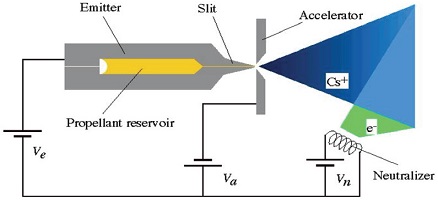
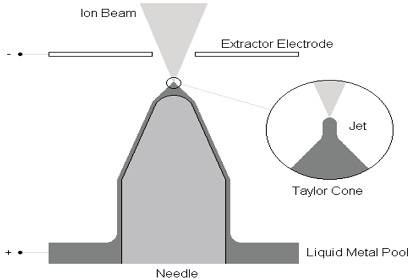
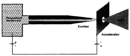
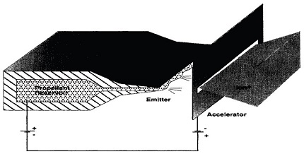
FEEP 추력기는 방출기(emitter), 가속기(accelerator), 중화기(neutralizer), 그리고 추진제 저장소(propellant reservoir)로 구성되어 있으며(Fig. 2), 액체 금속을 추진제로 사용한다. 액체 금속은 모세관력(capillary force)에 의해 방출기를 따라 이동하게 된다. 이때, 방출기와 가속기 사이에 높은 전위차가 가해지면, 방출기 팁(tip)에서 액체 금속의 표면장력과 전기장이 상호 작용하여 원뿔 모양의 형상이 생성되는데, 이를 테일러 원뿔(Taylor cone)이라 한다(Fig. 3). 이후 방출기 팁이 1010 V/m 정도의 전계 강도를 갖게 되면 액체 금속의 이온화가 일어난다. 즉, 추진제로 사용되는 액체 금속의 표면에서 전계방출에 의해 이온이 생성되는 원리이다. 발생된 이온은 전기장에 의해 100 km/s보다 높은 속도로 가속되어 추력기를 빠져나가고, 그 결과 1 μN∼1 mN 범위의 추력을 낼 수 있게 된다.
2.2 구성품
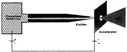
방출기는 액체 금속으로부터 이온을 추출하기 위한 FEEP 추력기의 핵심 구성품 중 하나이며, 대표적으로(1) 핀(pin) 또는 니들(needle)형, (2) 모세관(capillary)형, (3) 슬릿(slit)형으로 구분된다. 니들형은 방출기 외부 표면을 따라 액체 금속이 적셔지고, 반대로 모세관형과 슬릿형은 방출기 내부에서 액체 금속이 적셔지게 된다(Fig. 4-6).
Fig. 4, 5 형태의 단일 방출기는 전형적으로 수십 μN 수준의 추력을 발생시킨다[7]. 추력을 mN급 수준으로 증가시키려면 단일 방출기를 클러스터 시키거나 여러 개의 방출부(emission site)를 갖는 방출기, 즉 다중 방출기(multi emitter)를 사용하면 된다.
단일 방출기를 클러스터 하여 추력을 증가시키는 경우, 각각의 방출기에 대해 전원공급기를 따로 사용해야 하기 때문에 PPU(Power Processing Unit)가 커지게 되는 문제점이 있다. 그러나 다중 방출기를 사용하면 오직 하나의 전원공급기로 추력기 운용이 가능하다.
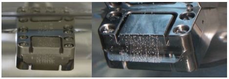
Fig. 6에서 볼 수 있듯이 다중 방출기 중 한 가지 방법으로 슬릿형 방출기가 있다. 슬릿형 방출기는 두 개의 금속판이 대칭 구조로 이루어져 있다. 일반적으로 유로의 간격 즉, 슬릿 폭은 1∼1.5 μm이고 슬릿 길이는 2 mm에서 7 cm 정도이다[6]. 슬릿 길이가 길어질수록 발생시킬 수 있는 추력이 커지며, 2 mm에서 7 cm의 슬릿 길이에 해당하는 추력 범위는 40 μN∼1.4 mN으로 알려진 바 있다[6]. 슬릿 길이 방향을 따라 여러 개의 테일러 원뿔을 가지기 때문에 mN 수준의 추력을 내기 위해서 니들형 방출기나 모세관형 방출기를 클러스터 시킬 필요가 없다. 슬릿형 방출기는 높은 추력 대 전력비를 갖는다는 장점이 있으나, 니들형 방출기, 모세관형 방출기와 달리 능동적인 추력 벡터링에 사용할 수 없다는 단점이 있다[4].
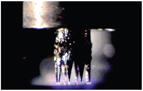
다중 방출기의 다른 방법으로 왕관(crown)형 방출기가 있다. 왕관형 방출기는 여러 개의 니들이 원형으로 배치되고 각각의 니들에서 테일러 원뿔이 부착되기 때문에 발생시킬 수 있는 추력이 증가하게 된다. 왕관 형상은 튜브 형태의 금속 가장자리가 원주 방향을 따라 잘리면서 만들어지는데, 가공 방법으로 스파크 침식(spark erosion) 기술이 있다[7]. Fig. 7은 8개의 니들을 가진 왕관형 방출기가 작동하는 모습을 보여주고 있다[7].
가속기는 추출기(extractor)라고 부르기도 하며, 방출기와 함께 전원공급기로부터 전력을 공급받아 이온을 추출하는데 필요한 전기장을 생성시키고, 전위차를 만들어줌으로써 이온을 가속시키는 역할을 한다. 방출기는 보통 양의 전위를 갖는 반면에 가속기는 음의 전위를 가지며, 방출기 팁으로부터 0.6 mm 정도 떨어진 매우 가까운 곳에 가속기가 위치하게 된다[6,8].
FEEP 추력기를 운용하는 동안 추력기에서 방출된 이온이 비행체 표면에 축적되면, 우주비행체 대전(spacecraft charging) 현상이 발생하여 비행체를 구성하는 전자 장비에 문제를 일으킬수 있다. 이를 방지하기 위해서 가속기를 지나 가속 중인 이온 영역에 전자를 공급하여 이온을 중성화시키는 용도로 중화기가 필요하다.
중화기로 열전자 음극(thermionic cathode)이 자주 쓰이는데, 이 방식은 열 필라멘트(hot filament)를 사용하여 전자를 방출하기 때문에 상대적으로 높은 전력이 요구된다[9-11]. 낮은 전력으로 사용 가능한 중화기는 크게 3가지 방식으로 저전력 열전자(low-power thermionic) 음극, 전계방출 어레이(field emission array) 음극, 그리고 탄소나노튜브(carbon nanotube) 음극이 있다. 저전력 열전자 음극으로는 혼합금속(mixed-metal) 음극과 scandate 음극이 적합하며, 전계방출 방식을 적용하면 가열 전력이 필요 없어서 요구되는 전력이 줄어들고 중화기를 소형화시킬 수 있게 된다[9-11]. 탄소나노튜브는 뛰어난 물성을 갖고 있기 때문에 이를 활용하면 강건성 높은 중화기를 제작할 수 있다[11].
추진제 저장소는 임무기간 동안 사용할 추진제를 충분히 저장해야 한다. FEEP 추력기는 높은 비추력을 갖기 때문에 추진제 소모가 매우 적다. 따라서 소형의 저장소가 적절하며, 모세관 현상을 유지시키기 위해서 추진제가 잘 적셔질 수 있는 재료로 추진제 저장소를 제작해야 한다. 또한, 저장소에서 방출기 팁으로의 추진제 공급이 원활히 이루어지도록 하기 위해 슬릿형 방출기의 경우 저장소 내부에 공급 채널을 추가하는 방법이 있다(Fig. 8)[10].
2.3 추진제
FEEP 추력기는 액체 금속을 추진제로 사용한다. 액체 금속 추진제를 선정할 때 주요 고려사항은 액적(droplet) 방출 정도, 원자 질량, 녹는점이다[6,8,9,12]. 전기장을 가했을 때 액체 금속이 액적으로 방출되면 가속기를 막아서 추력기 성능을 저하시키기 때문에 이온으로 방출될수록 좋다[13]. 원자 질량이 클수록 추력이 증가하고, 녹는점이 낮을수록 전력을 적게 사용할 수 있다. 이밖에도 추진제의 증기압이 낮을수록 증발이 잘 일어나 바람직하고, 추력기 및 주위 대기와 추진제 사이의 적합성을 고려해야 한다.
FEEP 추력기에 사용되는 액체 금속 추진제는 세슘(Cs), 인듐(In), 루비듐(Rb), 갈륨(Ga) 등이 있다. FEEP 추력기의 연구개발에 있어 가장 먼저 적용된 추진제는 세슘이다. 세슘은 일반 금속에 비해 29 °C의 낮은 녹는점, 높은 원자 질량, 우수한 젖음(wetting) 특성 등의 장점 때문에 FEEP 추력기에 적합한 추진제로 활용되었으나, 높은 반응성을 가져 우주비행체를 오염시킬 수 있는 문제점이 있다. 인듐은 세슘과 루비듐에 비해 화학적 위험성이 적다는 장점이 있으나, 녹는점이 156 °C에 이르러 액체 상태 유지를 위해 상대적으로 높은 전력을 소요로 하는 단점이 있다. 루비듐과 갈륨의 녹는점은 각각 39 °C, 30 °C로 적은 전력이 요구되며, 원자 질량이 작으므로 낮은 추력을 발생시키기 위해 사용할 수 있다. 각 추진제의 물성을 Table 2에 정리하였다.
2.4 개발 현황
FEEP 추력기는 1970년대부터 유럽을 중심으로 연구되었으며, 현재는 크게 이탈리아, 오스트리아, 독일에서 연구개발이 진행 중인 것으로 파악되었다.
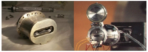
이탈리아의 Centrospazio에서 FEEP-5와 FEEP-50 추력기를 개발하였는데, 추진제는 세슘이고 슬릿형 방출기를 사용하였다[14,15]. 각 추력기의 성능을 Table 3에 정리하였으며, Fig. 9에서 FEEP-5 추력기를 보여주고 있다[14-17].
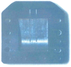
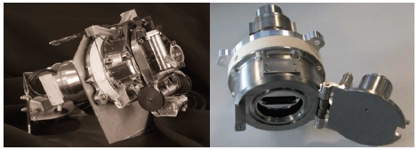
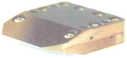
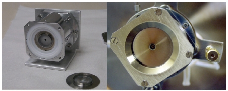
Centrospazio의 민간 이전으로 설립된 Alta사는 LISA(Laser Interferometer Space Antenna) 임무의 검증 단계인 LPF(LISA Pathfinder)에 사용할 추진기관으로 FEEP-150 추력기를 개발하였다(Fig. 10)[18-25]. FEEP-150 추력기는 슬릿형 방출기를 사용하고 추진제는 세슘이며, 추력 0.1∼150 μN, 비추력 3,000∼4,500 s, 소비전력 6 W의 성능을 가지고 있다[19]. Fig. 11과 12에서 Centrospazio/Alta가 개발한 슬릿형 방출기를 볼 수 있는데, Fig. 11은 FEEP-150 추력기에 사용된 방출기이다[10,23,24]. Fig. 13은 LPF에 사용한 FCA(FEEP Cluster Assembly)로 FEEP-150 추력기가 클러스터 되어 있는 모습을 보여주고 있다[25]. Alta사는 2014년에 SITAEL사에 인수되어 FEEP 추력기 연구개발을 진행하고 있다.
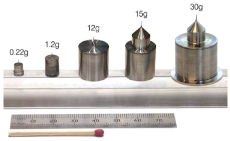
오스트리아의 ARC(Austrian Research Center)에서는 1980년대 후반부터 인듐을 사용한 LMIS(Liquid Metal Ion Source) 연구가 진행되었다[14,15,26]. Fig. 14에서 볼 수 있듯이 서로 다른 용량을 가진 인듐 LMIS가 개발되었는데, 최소 용량은 0.22 g, 최대 용량은 30 g이며, 방출기는 텅스텐으로 만든 니들형 방출기를 사용하였다[26].
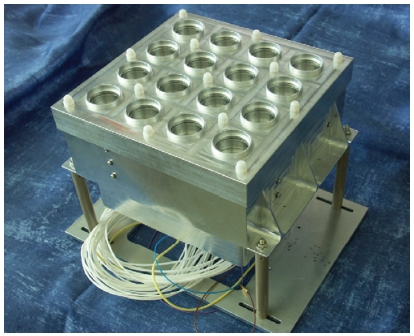
ARC에서 인듐 LMIS를 이용하여 제작한 추력기와 이에 해당하는 성능을 Table 4에 정리하였으며, 그중에서 InFEEP-100 추력기를 Fig. 15에서 확인할 수 있다[15,27,28]. Fig. 16은 GOCE(Gravity Field and Steady-State Ocean Circulation Explorer) 임무의 추진기관 후보 중 하나로 고려되었던 GOCE MTA(Micro Thruster Assembly)를 나타내고 있는데, 임무 요구조건을 만족시키기 위해 16개의 방출기가 클러스터 되었다[15].
방출기를 클러스터 할 때, 방출기마다 다른 전류-전압 특성을 보여주어 ARC는 하나의 전원공급기로 추력기를 운용하는 것에 어려움이 있었다. 하지만, 방출기가 높은 임피던스를 갖게 함으로써 방출기에서 나타나는 전류에 따른 전압 변화를 최소화시켜 문제를 해결하였다. 니들 팁의 직경을 2∼3 μm로 매우 뾰족하게 제작하고, 방출기와 전원공급기 사이에 pre-resistor를 연결하여 방출기의 임피던스를 높일 수 있었다[26].
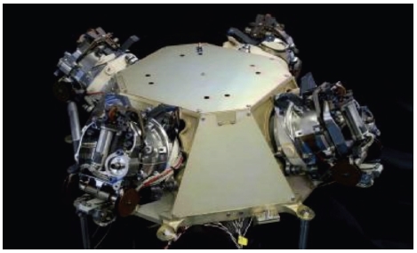
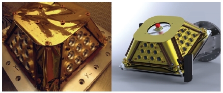
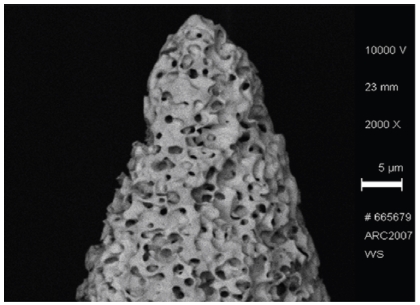
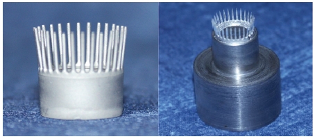
LPF의 추진기관으로 앞서 설명한 세슘-슬릿형 FCA 이외에 ARC에서 개발된 인듐-니들형 FCA가 있는데(Fig. 17), 이는 LPF의 보조 추진기관으로 사용되었다[30-37]. 인듐-니들형 FCA는 4개의 패널 각각에 15 g 용량의 인듐 LMIS 9개가 클러스터 되어 있으며, 하나의 고전압 전원공급기로 운용된다[32]. 또한, 인듐-니들형 FCA는 0.1∼100 μN의 추력 범위를 가지며, 25 μN으로 운용했을 때 5,841 s의 비추력을 보인다[32]. ARC는 소형이면서 더 많은 방출기를 갖는 FEEP 추력기를 만들고자 하였으며, 그로 인해 다공성 텅스텐을 이용한 왕관형 방출기가 개발되었다[26]. 28개의 니들을 가진 왕관형 방출기를 제작하고 시험하였는데, 모든 니들이 작동하였을 경우, 공칭추력은 0.4 mN으로 측정되었다[38]. 70개 이상의 니들을 가진 하나의 왕관형 방출기를 사용하거나, 28개의 니들을 가진 2∼3개의 왕관형 방출기를 클러스터 하여 1 mN급 추력을 발생시킬 수 있다[38]. Fig. 18에 다공성 텅스텐으로 만든 니들 팁을 나타내었으며, Fig. 19에서 왕관형 방출기를 보여주고 있다[26,38,39].
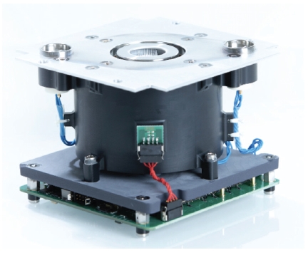
오스트리아의 FOTEC사에서 왕관형 방출기 기술을 바탕으로 IFM(Indium FEEP Multi emitter) Nano 추력기를 개발하였고, 이 추력기는 FOTEC사의 스핀아웃 기업인 ENPULSION사에 의해 상용화되었다[40-49]. IFM Nano 추력기는 2018년 Planet Labs사의 Flock-3p’ 위성을 시작으로 York Space Systems사의 Harbinger, Helios Wire사의 Sirion Pathfinder-2 등의 위성에 탑재된 바 있다. Fig. 20에서 IFM Nano 추력기를 보여주고 있으며, ENPULSION사의 추력기 모델 및 성능을 Table 5에 정리하였다[14,48].
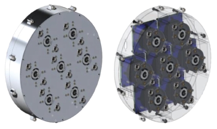
IFM Nano 추력기는 클러스터가 가능한데, Fig. 21에서 볼 수 있듯이 7개의 추력기를 클러스터 하였을 경우, 200 W 미만의 전력으로 2 mN이 넘는 추력을 얻을 수 있게 된다[49].
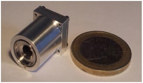
독일의 TU Dresden에서는 큐브위성의 자세제어를 목적으로 고도로 소형화된 NanoFEEP을 개발하였는데(Fig. 22), 0.05∼22 μN의 추력 범위를 가지며, 1∼2 μN의 평균추력으로 운용했을 때 6,000 s의 비추력을 보인다[5,50,51]. NanoFEEP은 다공성 텅스텐으로 만들어진 한 개의 니들형 방출기를 갖고 있으며, 소비전력을 줄이기 위해 녹는점이 30 °C인 갈륨을 추진제로 사용하였다[5,50,51].
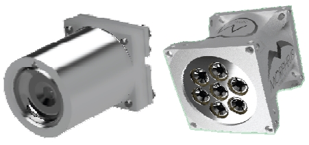
TU Dresden의 스핀오프 기업으로 Morpheus Space사가 설립되었고 FEEP 추력기 연구개발이 진행되고 있다. TU Dresden/Morpheus Space에서 개발한 NanoFEEP은 뷔르츠부르크 대학교의 UWE-4, 서울대학교의 SNUSAT-2 위성에 탑재된 바 있다. Fig. 23에서 Morpheus Space사의 NanoFEEP과 MultiFEEP을 보여주고 있으며, 각각의 성능을 Table 6에 정리하였다[52,53].
2.5 해석 및 시험
FEEP 추력기의 성능을 수치적으로 해석하기 위한 방법으로 PIC(Particle-In-Cell) 기법, 라그랑지안 입자 추적 모델 등이 사용된다[54-62]. PIC 기법은 오일러리안 기법으로 전자기장을 계산하고, 라그랑지안 기법으로 입자를 계산하는 이상유동(Two phase flow) 해석 방법으로서 Tajmar 등은 이를 통해 FEEP 추력기에서 방출되는 이온 빔의 특성을 해석하였다[54-58]. 또한, 유럽의 MICROSCOPE와 LPF 임무에서 PIC를 기반으로 하는 SPIS 소프트웨어를 활용하여 우주비행체와 FEEP 추력기 플룸(plume) 사이의 상호작용에 대한 연구를 수행한 바 있다[59-61]. IFM Nano 추력기를 개발한 FOTEC사는 라그랑지안 기반의 COMSOL 소프트웨어를 이용하여 성능 해석을 수행한 사례가 있으며, 이온 빔 궤적, 전위, 그리고 전기장 등에 대한 정보를 도출하였다[62].
FEEP 추력기의 시험은 추력 측정, 이온 빔 진단 등이 수행되며, 이러한 시험을 통해 추력기의 성능 파악 및 검증을 할 수 있다[27,50,62-82].
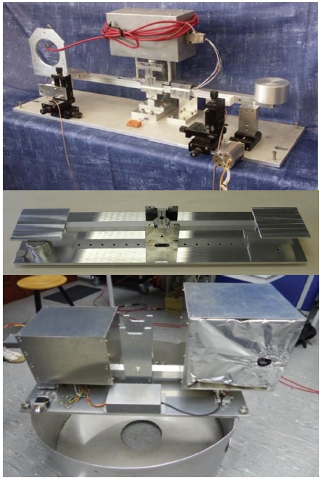
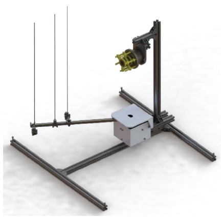
전기추력기의 미소 추력 측정은 크게 4가지로 진자(hanging pendulum) 방법, 역진자(inverted pendulum) 방법, 비틀림 진자(torsional pendulum) 방법, 그리고 정상상태 영위법(steady-state null balance)이 있는데, 비틀림 진자 방법은 비틀림 균형(torsion balance) 방법이라고 부르기도 한다[63-65]. FEEP 추력기의 추력 측정에는 비틀림 균형 방법이 주로 사용되며, Fig. 24는 오스트리아와 독일에서 개발된 비틀림 균형 장비를 보여주고 있다[50,67,68].
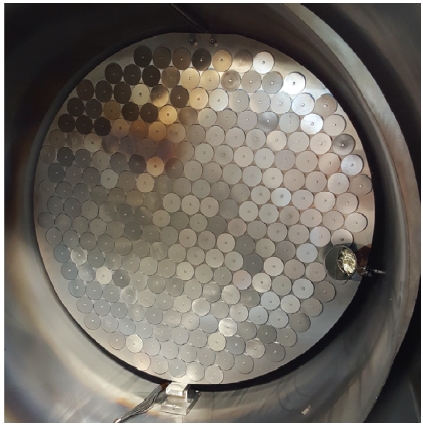
이온 빔 진단 방법으로는 탐침(probe), 패러데이 컵(Faraday cup, FC), 그리고 지연전위분석기(Retarding Potential Analyzer, RPA) 등이 사용된다[27,74-82]. 탐침을 이용한 측정 장비를 Fig. 25-28에서 확인할 수 있는데, Fig. 25는 플룸 특성을 파악하기 위한 목적으로 Centrospazio에서 개발된 장비이며[27,75], Fig. 26은 ARC에서 제작한 이온 빔 분포 측정 장비를 나타내고 있다[76-78]. TU Dresden에서는 Fig. 27의 장비를 개발하였고, 탄소 벨벳(carbon-velvet) 탐침을 사용하여 NanoFEEP의 플룸을 측정하였다[79]. 또한, FOTEC사는 세그먼트 수집기(segmented collector)를 개발하여 IFM Nano 추력기의 이온 전류 밀도 분포를 측정하였다[80]. FOTEC사의 세그먼트 수집기는 주석으로 만들어진 252개의 원형 평면 탐침으로 이루어져 있으며, Fig. 28에 이 장비를 나타내었다[80].
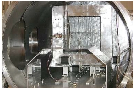
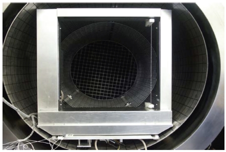
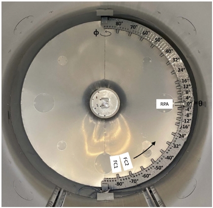
패러데이 컵과 지연전위분석기를 이용한 사례로는 FOTEC사에서 개발한 빔 진단 장비가 있는데, 23개의 패러데이 컵과 1개의 지연전위분석기로 구성되어 있다[62,81,82]. 이를 이용해 IFM Nano 추력기의 이온 에너지 분포 및 이온 전류 밀도 분포를 측정한 바 있다[62]. Fig. 29와 Fig. 30에서 FOTEC사의 패러데이 컵, 지연전위분석기, 그리고 빔 진단 장비를 보여주고 있다[62,81,82].
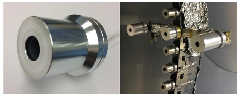
Faraday cup(left), Three RPA mounted horizontally at the center for RPA design selection(right)[81,82].
3. 결 론
FEEP 추력기의 전반적인 내용에 대해 소개하고 개발 현황과 해석 및 시험 방법에 대해 살펴보았다. FEEP 추력기는 추진제의 이온화가 전계방출로 이루어지고, 추진제가 모세관력에 의해 공급되기 때문에 밸브와 가압 장치가 필요 없어서 고도의 소형화가 가능하다. 다양한 형태의 방출기 중에서 슬릿형 방출기와 니들형 방출기 및 왕관형 방출기가 주로 연구, 개발되고 있다. 추력기의 효율적인 설계와 성능 분석을 위해 PIC 기법, 라그랑지안 입자 추적 모델 등을 활용한 시뮬레이션이 수행되고 있으며, 추력 측정 장비와 이온 빔 진단 장비 등의 성능 측정 장비가 개발되고 있다. 우리나라에서도 군집 초소형 위성에 대한 관심과 연구개발이 지속적으로 증가하는 추세이지만, 초소형 위성용 전기추력기 연구는 다소 부족한 실정이다. 향후 국내에서 군집 초소형 위성 운용 시 정밀 제어가 가능한 FEEP 추력기를 탑재하면 다양한 임무를 성공적으로 수행할 수 있을 것으로 기대되며, 관련 연구의 필요성을 제안한다.
References
- “Euroconsult’s small-satellite launch forecast,” retrieved 26 Jun. 2021 from https://spacenews.com/analysis-are-smallsats-entering-the-maturity-stage/, .
- Moon, H. J., “Electric Propulsion,” Journal of the Korean Society of Propulsion Engineers, Vol. 12, No. 3, pp. 76-86, 2008.
-
Kim, H., Kim, S. K. and Won, S. H., “Current Status and Trends of Research and Development on Electric Thruster, Part Ⅰ: Overseas,” Journal of the Korean Society of Propulsion Engineers, Vol. 23, No. 6, pp. 95-108, 2019.
[https://doi.org/10.6108/KSPE.2019.23.6.095]

- Badami, M. A., “Design of a FEEP Thruster for Micro-/Nano-Satellites,” M.S. Thesis, Department of Computer Science, Electrical and Space Engineering, Lulea University of Technology, Lulea, Sweden, 2019.
- Bock, D., Bethge, M. and Tajmar, M., “Highly miniaturized FEEP thrusters for CubeSat applications,” Proceedings of the 4th Spacecraft Propulsion Conference, Cologne, Germany, 2967498, May 2014.
-
Ketsdever, A. D. and Micci, M. M., Micropropulsion for small spacecraft, 1st ed., American Institute of Aeronautics and Astronautics, Inc., Reston, V.A., U.S.A., Ch. 3, 2000.
[https://doi.org/10.2514/4.866586]

-
Tajmar, M., Genovese, A., Buldrini, N. and Steiger, W., “Miniaturized Indium-FEEP Multiemitter Design and Performance,” NanoTech 2002- “At the Edge of Revolution”, Houston, T.X., U.S.A., AIAA 2002-5718, Sep. 2002.
[https://doi.org/10.2514/6.2002-5718]

- Bharti, M. K. and Chalia, S., “Literature study of field emission electric propulsion microthruster,” International Research Journal of Engineering and Technology, Vol. 4, No. 5, pp. 2777-2781, 2017.
-
Mitterauer, J., “Micropropulsion for small spacecraft: a new challenge for field effect electric propulsion and microstructured liquid metal ion sources,” Surface and Interface Analysis, Vol. 36, No. 5-6, pp. 380-386, 2004.
[https://doi.org/10.1002/sia.1693]

- Fernando, W. C. P., “FEEP thruster nano-satellite applications,” Ph.D. Thesis, Department of Power, Propulsion and Aerospace Engineering, Cranfield University, Cranfield, U.K., 2004.
-
Tajmar, M., “Survey on FEEP Neutralizer Options,” 38th AIAA/ASME/SAE/ASEE Joint Propulsion Conference and Exhibit, Indianapolis, I.N., U.S.A., AIAA 2002-4243, Jul. 2002.
[https://doi.org/10.2514/6.2002-4243]

-
Mitterauer, J., “Indium: An alternative propellant for FEEP-thrusters,” 37th AIAA/ASME/SAE/ASEE Joint Propulsion Conference and Exhibit, Salt Lake City, U.T., U.S.A., AIAA 2001-3792, Jul. 2001.
[https://doi.org/10.2514/6.2001-3792]

- VanderWyst, A. S., “Field Emission Electric Propulsion Thruster Modeling and Simulation,” Ph.D. Dissertation, Department of Aerospace Engineering, University of Michigan, Ann Arbor, M.I., U.S.A., 2006.
- Mani, K. V., “Combined chemical-electric propulsion design and hybrid trajectories for stand-alone deep-space CubeSats,” Ph.D. Dissertation, Department of Aerospace Science and Technology, Politecnico di Milano, Milano, Italy, 2020.
- Mueller, J., Hofer, R. and Ziemer, J., “Survey of propulsion technologies applicable to cubesats,” NASA TR 10-1646, 2010.
- Nicolini, D., Chesta, E., Gonzalez del Amo, J., Saccoccia, G., Hughes, E. and Oldfield, S., “FEEP-5 thrust validation in the 10–100 µN range with a simple nulled-pendulum thrust stand: integration procedures,” 27th International Electric Propulsion Conference, Pasadena, C.A., U.S.A., IEPC-01-288, Oct. 2001.
- Marcuccio, S., Giannelli, S. and Andrenucci, M., “Attitude and orbit control of small satellites and constellations with feep thrusters,” Proceedings of the 25th Electric Propulsion Conference, Cleveland, O.H., U.S.A., IEPC-97-188, Aug. 1997.
- Paita, L., Cesari, U., Nania, F., Priami, L., Rossodivita, A., Giusti, N., Andrenucci, M. and Estublier, D., “Alta FT-150: the thruster for LISA pathfinder and LISA/NGO missions,” Proceedings of the 9th LISA Symposium, Paris, France, pp. 245-249, May 2012.
- Paita, L., Ceccanti, F., Spurio, M., Cesari, U., Priami, L., Nania, F., Rossodivita, A. and Andrenucci, M., “Alta’s FT-150 FEEP microthruster: development and qualification status,” 31st International Electric Propulsion Conference, Ann Arbor, M.I., U.S.A., IEPC-2009-186, Sep. 2009.
-
Biagioni, L., Ceccanti, F., Saverdi, M., Saviozzi, M. and Andrenucci, M., “Qualification status of the FEEP-150 electric micropropulsion subsystem,” 41st AIAA/ASME/SAE/ASEE Joint Propulsion Conference and Exhibit, Tucson, A.Z., U.S.A., AIAA 2005-4261, Jul. 2005.
[https://doi.org/10.2514/6.2005-4261]

- Andrenucci, M., Biagioni, L., Ceccanti, F., Saviozzi, M. and Nicolini, D., “Endurance Tests of 150 μN FEEP Microthrusters,” 29th International Electric Propulsion Conference, Princeton, N.J., U.S.A., IEPC-2005-183, Nov. 2005.
-
Massotti, L. and Canuto, E. S., “Emerging technologies in the ESA science and earth observation programme,” 12th IEEE International Conference on Emerging Technologies and Factory Automation, Patras, Greece, pp. 69-76, Sep. 2007.
[https://doi.org/10.1109/EFTA.2007.4416755]

-
Marcuccio, S., Giusti, N. and Pergola, P., “Slit FEEP thruster performance with ionic liquid propellant,” 49th AIAA/ASME/SAE/ASEE Joint Propulsion Conference and Exhibit, San Jose, C.A., U.S.A., AIAA 2013-4034, Jul. 2013.
[https://doi.org/10.2514/6.2013-4034]

- Nicolini, D., “LISA Pathfinder field emission thruster system development program,” 30th International Electric Propulsion Conference, Florence, Italy, IEPC-2007-363, Sep. 2007.
- “Laser Interferometer Space Antenna,” retrieved 26 Jul. 2021 from https://sci.esa.int/documents/33859/36320/1567256647974-LISA_status_CV_downselection_Paris_030211_final.pdf, .
-
Tajmar, M., Scharlemann, C., Genovese, A., Buldrini, N., Steiger, W. and Vasiljevich, I., “Liquid-metal-ion source development for space propulsion at ARC,” Ultramicroscopy, Vol. 109, No. 5, pp. 442-446, 2009.
[https://doi.org/10.1016/j.ultramic.2008.10.009]

- Nicolini, D., Chesta, E. and Gonzalez del Amo, J., “Plume characteristics of the Indium needle emitter (InFEEP) thruster,” 27th International Electric Propulsion Conference, Pasadena, C.A., U.S.A., IEPC-01-291, Oct. 2001.
- Marrese-Reading, C., Polk, J., Mueller, J., Owens, A., Tajmar, M., Spindt, C. and Fink, R., “In-FEEP thruster ion beam neutralization with thermionic and field emission cathodes,” 27th International Electric Propulsion Conference, Pasadena, C.A., U.S.A., IEPC-01-290, Oct. 2001.
-
Scharlemann, C. and Tajmar, M., “Development of propulsion means for microsatellites,” 43rd AIAA/ASME/SAE/ASEE Joint Propulsion Conference and Exhibit, Cincinnati, O.H., U.S.A., AIAA 2007-5184, Jul. 2007.
[https://doi.org/10.2514/6.2007-5184]

-
Tajmar, M., Scharlemann, C., Genovese, A., Buldrini, N., Boss, M., Frueholz, H. and Killinger, R., “Indium FEEP micropropulsion subsystem for LISA Pathfinder,” 42nd AIAA/ASME/SAE/ASEE Joint Propulsion Conference and Exhibit, Sacramento, C.A., U.S.A., AIAA 2006-4826, Jul. 2006.
[https://doi.org/10.2514/6.2006-4826]

- Scharlemann, C., Genovese, A., Schnitzer, R., Buldrini, N., Sattler, P., Tajmar, M., Killinger, R. and Früholz, H., “Test results of the qualification tests for the In-FEEP Technology for LISA PF,” 31st International Electric Propulsion Conference, Ann Arbor, M.I., U.S.A., IEPC-2009-050, Sep. 2009.
- Tajmar, M., “Overview of indium LMIS for the NASA-MMS mission and its suitability for an In-FEEP thruster on LISA,” 32nd International Electric Propulsion Conference, Wiesbaden, Germany, IEPC-2011-009, Sep. 2011.
-
Scharlemann, C., Buldrini, N., Killinger, R., Jentsch, M., Polli, A., Ceruti, L., Serafini, L., DiCara, D. and Nicolini, D., “Qualification test series of the indium needle FEEP micro-propulsion system for LISA Pathfinder,” Acta Astronautica, Vol. 69, No. 9-10, pp. 822-832, 2011.
[https://doi.org/10.1016/j.actaastro.2011.05.037]

-
Scharlemann, C., Genovese, A., Buldrini, N., Schnitzer, R., Tajmar, M., Früholz, H. and Killinger, R., “Development and test of an indium FEEP micropropulsion subsystem for LISA pathfinder,” 43rd AIAA/ASME/SAE/ASEE Joint Propulsion Conference and Exhibit, Cincinnati, O.H., U.S.A., AIAA 2007-5251, Jul. 2007.
[https://doi.org/10.2514/6.2007-5251]

- Scharlemann, C., Genovese, A., Buldrini, N., Schnitzer, R., Tajmar, M., Früholz, H. and Killinger, R., “Status of the indium FEEP micropropulsion subsystem development for LISA pathfinder,” 30th International Electric Propulsion Conference, Florence, Italy, IEPC-2007-122, Sep. 2007.
-
Scharlemann, C., Genovese, A., Buldrini, N., Schnitzer, R. and Tajmar, M., “In-FEEP qualification test program for LISA pathfinder,” 44th AIAA/ASME/SAE/ASEE Joint Propulsion Conference and Exhibit, Hartford, C.T., U.S.A., AIAA 2008-4825, Jul. 2008.
[https://doi.org/10.2514/6.2008-4825]

-
Scharlemann, C., Genovese, A., Schnitzer, R., Buldrini, N., Sattler, P. and Tajmar, M., “In-FEEP endurance test for LISA PF,” 45th AIAA/ASME/SAE/ASEE Joint Propulsion Conference and Exhibit, Denver, C.O., U.S.A., AIAA 2009-5093, Aug. 2009.
[https://doi.org/10.2514/6.2009-5093]

-
Vasiljevich, I., Tajmar, M., Grienauer, W., Plesescu, F., Buldrini, N., Gonzalez del Amo, J., Carnicero Domunguez, B. and Betto, M., “Development of an indium mN-FEEP thruster,” 44th AIAA/ASME/SAE/ASEE Joint Propulsion Conference and Exhibit, Hartford, C.T., U.S.A., AIAA 2008-4534, Jul. 2008.
[https://doi.org/10.2514/6.2008-4534]

-
Tajmar, M., Vasiljevich, I. and Grienauer, W., “High current liquid metal ion source using porous tungsten multiemitters,” Ultramicroscopy, Vol. 111, No. 1, pp. 1-4, 2010.
[https://doi.org/10.1016/j.ultramic.2010.09.005]

- Reissner, A., Buldrini, N., Seifert, B., Hörbe, T., Plesescu, F. and Scharlemann, C., “Introducing very high Δv Capability to Nanosats and Cubesats,” Joint Conference of 30th ISTS, 34th IEPC and 6th NSAT, Kobe, Japan, IEPC-2015-396/ISTS-2015-b-396, Jul. 2015.
-
Reissner, A., Buldrini, N., Seifert, B., Hörbe, T., Plesescu, F., Gonzalez del Amo, J. and Massotti, L., “10 000 h Lifetime Testing of the mN-FEEP Thruster,” 52nd AIAA/SAE/ ASEE Joint Propulsion Conference, Salt Lake City, U.T., U.S.A., AIAA 2016-5045, Jul. 2016.
[https://doi.org/10.2514/6.2016-5045]

-
Jelem, D., Seifert, B., Sypniewski, R., Buldrini, N. and Reissner, A., “Performance mapping and qualification of the IFM Nano thruster EM for in orbit demonstration,” 53rd AIAA/SAE/ASEE Joint Propulsion Conference, Atlanta, G.A., U.S.A., AIAA 2017-4887, Jul. 2017.
[https://doi.org/10.2514/6.2017-4887]

- Massotti, L., Gonzalez del Amo, J., Aschbacher, J., Silvestrin, P., Reissner, A. and Seifert, B., “The ESA Earth Observation Programme activities for the design, development and qualification of the mN-FEEP thruster,” 36th International Electric Propulsion Conference, Vienna, Austria, IEPC-2019-686, Sep. 2019.
- Reissner, A., Seifert, B., Jelem, D. and Sypniewski, R., “EFFICIENT DE-ORBITING OF MICRO- AND NANO SATELLITES USING THE IFM NANO THRUSTER,” 7th European Conference on Space Debris, Darmstadt, Germany, Apr. 2017.
- Krejci, D., Reissner, A., Seifert, B., Jelem, D., Hörbe, T., Plesescu, F., Friedhoff, P. and Lai, S., “Demonstration of the ifm nano feep thruster in low earth orbit,” 4S Symposium, Sorrento, Italy, Jun. 2018.
- Krejci, D., Hugonnaud, V., Schönherr, T., Little, B., Reissner, A., Seifert, B., Koch, Q., Bosch-Borràs, E. and González del Amo, J., “Full performance mapping of the IFM Nano Thruster, including direct thrust measurements,” Journal of small satellites, Vol. 8, No. 2, pp. 881-893, 2019.
- Schönherr, T., Little, B., Krejci, D., Reissner, A. and Seifert, B., “Development, production, and testing of the IFM nano FEEP thruster,” 36th International Electric Propulsion Conference, Vienna, Austria, IEPC-2019-362, Sep. 2019.
- “ENPULSION Thruster Comparison Table,” retrieved 26 Jul. 2021 from https://www.enpulsion.com/order/, .
-
Seifert, B., Reissner, A., Jelem, D. and Hörbe, T., “Development of a low cost PPU for FEEP electric propulsion using cots components,” 11th European Space Power Conference, Thessaloniki, Greece, 15003, Oct. 2016.
[https://doi.org/10.1051/e3sconf/20171615003]

- Bock, D., Ebert, M., Roesler, F., Koessling, M. and Tajmar, M., “Development and testing of field emission thrusters at TU dresden,” Proceedings of the 5th Russian-German Conference on Electric Propulsion, Dresden, Germany, pp. 1-16, Sep. 2014.
- Bock, D., Kramer, A., Bangert, P., Schilling, K. and Tajmar, M., “NanoFEEP - Highly Miniaturized FEEP Propulsion System for Attitude and Orbit Control of Cubesats,” Proceedings of the 5th Space Propulsion Conference, Rome, Italy, pp. 2-6, May 2016.
- “Morpheus Space,” retrieved 26 Jul. 2021 from https://www.morpheus-space.com/, .
- “M-Space Products,” retrieved 26 Jul. 2021 from https://www.morpheus-space.com/static/MSWeb/documents/M-Space%20Products.pdf, .
- Tajmar, M., Rüdenauer, F. and Fehringer, M., “Backflow Contamination of Indium Liquid-Metal Ion Emitters (LMIE): Numerical Simulations,” 26th International Electric Propulsion Conference, Kitakyushu, Japan, IEPC-99-070, Oct. 1999.
-
Tajmar, M., Mitterauer, J. and Wang, J., “Field-Emission-Electric-Propulsion (FEEP) plasma modeling: 3-D full particle simulations,” 35th AIAA/ASME/SAE/ASEE Joint Propulsion Conference and Exhibit, Los Angeles, C.A., U.S.A., AIAA 99-2298, Jun. 1999.
[https://doi.org/10.2514/6.1999-2298]

-
Tajmar, M. and Wang, J., “Three-dimensional numerical simulation of field-emission-electric-propulsion neutralization,” Journal of Propulsion and Power, Vol. 16, No. 3, pp. 536-544, 2000.
[https://doi.org/10.2514/2.5602]

-
Tajmar, M. and Wang, J., “Three-dimensional numerical simulation of field-emission-electric-propulsion backflow contamination,” Journal of Spacecraft and Rockets, Vol. 38, No. 1, 2001, pp. 69-78, 2001.
[https://doi.org/10.2514/2.3656]

-
Tajmar, M., Steiger, W. and Genovese, A., “Indium FEEP Thruster beam diagnostics, analysis and simulation,” 37th AIAA/ASME/SAE/ASEE Joint Propulsion Conference and Exhibit, Salt Lake City, U.T., U.S.A., AIAA 2001-3790, Jul. 2001.
[https://doi.org/10.2514/6.2001-3790]

- Andersson, B., Nicolini, D. and Gengembre, E., “SPIS Modeling of FEEP thrusters for LISA Pathfinder,” 30th International Electric Propulsion Conference, Florence, Italy, IEPC-2007-362, Sep. 2007.
-
Roussel, J.-F., Tondu, T., Mateo-Velez, J.-C., Chesta, E., D’Escrivan, S. and Perraud, L., “Modeling of FEEP plume effects on MICROSCOPE spacecraft,” IEEE Transactions on Plasma Science, Vol. 36, No. 5, pp. 2378-2386, 2008.
[https://doi.org/10.1109/TPS.2008.2002541]

- Villemant, M., Sarrailh, P. and Hess, S., “Droplets emission from FEEP and colloids thrusters: modelling of droplets dynamics and interaction with spacecraft body,” 36th International Electric Propulsion Conference, Vienna, Austria, IEPC-2019-196, Sep. 2019.
-
Mühlich, N. S., Seifert, B. and Aumayr, F., “IFM Nano Thruster performance studied by experiments and numerical simulations,” Journal of Physics D: Applied Physics, Vol. 54, No. 9, p. 095203, 2020.
[https://doi.org/10.1088/1361-6463/abc84c]

-
Yang, Y.-X., Tu, L.-C., Yang, S.-Q. and Luo, J., “A torsion balance for impulse and thrust measurements of micro-Newton thrusters,” Review of Scientific Instruments, Vol. 83, No. 1, p. 015105, 2012.
[https://doi.org/10.1063/1.3675576]

- Polk, J. E., Pancotti, A., Haag, T., King, S., Walker, M., Blakely, J. and Ziemer, J., “Recommended practices in thrust measurements,” 33rd International Electric Propulsion Conference, Washington, D.C., U.S.A., IEPC-2013-440, Oct. 2013.
-
Polk, J. E., Pancotti, A., Haag, T., King, S., Walker, M., Blakely, J. and Ziemer, J., “Recommended practice for thrust measurement in electric propulsion testing,” Journal of Propulsion and Power, Vol. 33, No. 3, pp. 539-555, 2017.
[https://doi.org/10.2514/1.B35564]

-
Marhold, K. and Tajmar, M., “Micronewton thrust balance for indium FEEP thrusters,” 41st AIAA/ASME/SAE/ASEE Joint Propulsion Conference and Exhibit, Tucson, A.Z., U.S.A., AIAA 2005-4387, Jul. 2005.
[https://doi.org/10.2514/6.2005-4387]

- Marhold, K. and Tajmar, M. “Direct thrust measurement of In-FEEP clusters,” 29th International Electric Propulsion Conference, Princeton, N.J., U.S.A., IEPC-2005-235, Nov. 2005.
- Seifert, B., Reissner, A., Buldrini, N., Plesescu, F. and Scharlemann, C., “Development and verification of a µN thrust balance for high voltage electric propulsion systems,” 33rd International Electric Propulsion Conference, Washington, D.C., U.S.A., IEPC-2013-208, Oct. 2013.
- Nicolini, D., Frigot, P.-E., Musso, F., Cesare, S., Castorina, G., Ceruti, L., Bartola, F., Zanella, P., Ceccanti, F., Priami, L. and Paita, L., “Direct thrust and thrust noise measurements on the LISA pathfinder field emission thruster,” 31st International Electric Propulsion Conference, Ann Arbor, M.I., U.S.A., IEPC-2009-183, Sep. 2009.
-
Rocca, S., Menon, C. and Nicolini, D., “FEEP micro-thrust balance characterization and testing,” Measurement Science and Technology, Vol. 17, No. 4, pp. 711-718, 2006.
[https://doi.org/10.1088/0957-0233/17/4/016]

- Paolucci, F., d’Agostino, L. and Burgoni, S., “Design and performance study of a micronewton thrust stand for FEEP,” Proceedings of the 2nd European Spacecraft Propulsion Conference, Noordwijk, Netherlands, SP-398, Aug. 1997.
-
Boccaletto, L. and d’Agostino, L., “Design and testing of a micro-Newton thrust stand for FEEP,” 36th AIAA/ASME/SAE/ASEE Joint Propulsion Conference and Exhibit, Huntsville, A.L., U.S.A., AIAA 2000-3268, Jul. 2000.
[https://doi.org/10.2514/6.2000-3268]

-
Merkowitz, S. M., Maghami, P. G., Sharma, A., Willis, W. D. and Zakrzwski, C. M., “A μNewton thrust-stand for LISA,” Classical and Quantum Gravity, Vol. 19, No. 7, pp. 1745-1750, 2002.
[https://doi.org/10.1088/0264-9381/19/7/370]

-
Marcuccio, S., Genovese, A. and Andrenucci, M., “Experimental performance of field emission microthrusters,” Journal of Propulsion and Power, Vol. 14, No. 5, pp. 774-781, 1998.
[https://doi.org/10.2514/2.5340]

-
Nicolini, D., Marcuccio, S. and Andrenucci, M., “3-D plume characterization of a FEEP thruster,” 36th AIAA/ASME/SAE/ASEE Joint Propulsion Conference and Exhibit, Huntsville, A.L., U.S.A., AIAA 2000-3269, Jul. 2000.
[https://doi.org/10.2514/6.2000-3269]

-
Tajmar, M., Genovese, A. and Steiger, W., “Indium field emission electric propulsion microthruster experimental characterization,” Journal of Propulsion and Power, Vol. 20, No. 2, pp. 211-218, 2004.
[https://doi.org/10.2514/1.9247]

- Tajmar, M., Marhold, K. and Kropatschek, S., “Three-dimensional In-FEEP plasmadiagnostics,” 28th International Electric Propulsion Conference, Toulouse, France, IEPC-03-161, Mar. 2003.
-
Tajmar, M., Marhold, K., Kropatschek, S. and Rudolf, F., “Advanced 3D Plasma Diagnostic for the Indium FEEP Microthruster,” 39th AIAA/ASME/SAE/ASEE Joint Propulsion Conference and Exhibit, Huntsville, A.L., U.S.A., AIAA 2003-4569, Jul. 2003.
[https://doi.org/10.2514/6.2003-4569]

- Bock, D., Laufer, P., Paries, F., Kopnarski, M. and Tajmar, M., “Plume characterization of NanoFEEP thrusters with a plasma diagnostics facility using carbon-velvet probes,” 35th International Electric Propulsion Conference, Atlanta, G.A., U.S.A., IEPC-2017-471, Oct. 2017.
-
Jelem, D., Reissner, A., Seifert, B., Buldrini, N., Wilding, L. and Krejci, D., “Direct thrust and plume divergence measurements of the IFM Nano Thruster,” Advances in Space Research, Vol. 62, No. 12, pp. 3398-3404, 2018.
[https://doi.org/10.1016/j.asr.2018.06.028]

- Keerl, S., Engel, W., Mühlich, N. S., Fries, J., Seifert, B., Ceribas, E., Koopmans, R.-J. and Jelem, D., “Two-dimensional plasma plume density characterisation of the IFM Nano Thruster,” 36th International Electric Propulsion Conference, Vienna, Austria, IEPC-2019-566, Sep. 2019.
- Mühlich, N. S., Keerl, S., Engel, W., Ceribas, E. and Koopmans, R.-J., “Retarding potential analyser development for low density FEEP Thruster beam diagnostics,” 36th International Electric Propulsion Conference, Vienna, Austria, IEPC-2019-445, Sep. 2019.
