탄화수소 항공유의 흡열반응 성능향상을 위한 촉매 분해 및 수증기 개질 기술분석
Copyright Ⓒ The Korean Society of Propulsion Engineers
This is an Open-Access article distributed under the terms of the Creative Commons Attribution Non-Commercial License(http://creativecommons.org/licenses/by-nc/3.0) which permits unrestricted non-commercial use, distribution, and reproduction in any medium, provided the original work is properly cited.
초록
극초음속 비행체용 능동냉각시스템의 전체적인 운용 성능을 결정하는 주요 요소는 크게 탄화수소 흡열연료, 재생냉각 채널, 시스템 소재 및 구조로 구분되며, 그 중에서도 효율적인 재생냉각시스템 개발을 위한 일련의 연구는 탄화수소 항공유의 흡열반응 성능 향상으로부터 시작된다. 따라서 이전 연구에서는 탄화수소 항공유 자체의 흡열분해 특성에 대한 광범위한 연구 동향을 정리하였으며, 본 연구에서는 그에 대한 후속 연구로서 효과적인 흡열분해 특성 개선 및 성능 향상 방안으로 다양하게 시도되고 있는 촉매 분해와 수증기 개질 연구들에 대한 세부기술 분석을 수행하였다.
Abstract
Fundamental parameters describing overall operational characteristics of active cooling systems of a hypersonic flight vehicle are mainly classified into endothermic hydrocarbon fuels, regenerative cooling channels, and materials and system structures. Of primary importance is the improvement of endothermic performance of hydrocarbon aviation fuels in a series of studies developing efficient regenerative cooling systems. In a previous study, therefore, an extensive technical analysis has been carried out on thermal decomposition characteristics of liquid hydrocarbon fuels. As a subsequent study, catalytic cracking and steam reforming technologies have been reviewed to find a way for the improvement of endothermic reaction performance of hydrocarbon aviation fuels.
Keywords:
Hypersonic Vehicle, Scramjet Engine, Regenerative Cooling, Hydrocarbon Pyrolysis키워드:
극초음속 비행체, 스크램제트 엔진, 재생 냉각, 탄화수소 열분해1. 서 론
극초음속 순항 비행체는 지구 대기권 내에서 마하 5 이상의 속도로 순항하는 비행체로서[1], 실용화에 성공할 경우 2시간 이내에 태평양 횡단이 가능하므로 민간용으로는 반나절 동안에 대륙간(inter-continental) 이동을 할 수 있는 극초음속 여객기로, 군사용으로는 원거리 긴급(time-critical) 표적을 효과적으로 타격하는 극초음속 유도무기로 사용이 가능하다. 전세계적으로 극초음속 비행체에 대한 관심이 증가하고 있는 가운데, 미국, 중국, 러시아 등 강대국에서는 미래 전장 및 항공산업의 게임 체인저(game changer)로써 극초음속 비행체를 개발하기 위한 연구를 활발하게 진행하고 있으며, 특히 최근에는 러시아의 지르콘(Zircon), 중국의 WU-14 (DF-ZF), 인도의 브라모스(Brahmos)-II 등 그간 개발된 극초음속 미사일을 경쟁적으로 공개하였을 뿐만 아니라, 2019년에 미국은 국방예산 중 극초음속 무기 개발비를 전년 대비 136% 증가시킨 2억 5700만 달러로 책정하였다[2].
극초음속 순항비행체용 추진기관으로 사용되는 스크램제트 엔진은 대기 중의 공기를 초음속으로 흡입하고 연소실 내에서도 초음속을 유지한 상태에서 연료를 연소시켜 추력을 발생시키므로, 대기권 내에서 로켓 추진기관 대비 높은 비추력 특성과 초음속에서 극초음속까지의 광범위한 속도 영역에서의 운용 유연성을 가지므로 매우 효율적이고 효과적이다[1,3]. 그러나 이러한 스크램제트 엔진을 이용한 극초음속 순항 비행이 가능하기 위해서는 여러 가지 기술적인 난제를 해결하여야 하는데, 그중 하나는 고속 비행으로 인한 동체의 공력가열 및 엔진 연소실의 고온가열 문제로서, 비행체가 마하 5의 속도로 비행하는 경우 엔진 연소실은 2000℃ 이상으로 상승하므로[4] 현재까지 개발된 어떠한 고온 소재도 그대로는 적용이 불가능하다.
실용적인 스크램제트 엔진 개발을 위하여 극복해야만 하는 또 하나의 문제는 충격파 열(shock-train)이 동반되는 복잡하고 매우 빠른 초음속 공기 유동 내에서 탄화수소 액체 연료를 효과적으로 혼합하고 연소시키는 문제인데[1], 예를 들면 마하 5로 비행하는 경우 연소실 입구 공기 속도는 마하 2 내외이며 따라서 공기가 연소실에 체류하는 시간은 불과 3 밀리초 내외이므로 극히 짧은 시간 동안에 연료의 분사/증발/혼합/연소가 모두 이루어져야만 한다[1,5].
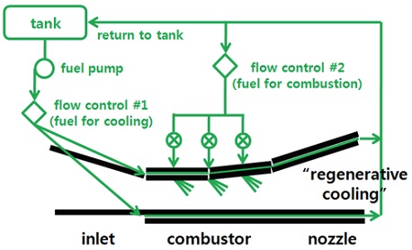
이와 같은 극초음속 비행체 내외부의 극심한 가열 문제를 해결함과 동시에 초음속으로 유입되어 지나가는 공기의 짧은 연소실 체류시간 동안에 효과적으로 연료를 연소시키기 위하여, 탑재된 액체 탄화수소 연료를 냉매로 이용하여 동체와 엔진을 냉각하는 능동재생냉각 방식이 대안으로 연구되어 왔다[1,6-8]. 재생냉각시스템의 기본적인 아이디어는 액체 탄화수소 연료의 흡열 반응을 이용하여 Fig. 1에 보이는 바와 같이 연료를 냉각이 필요한 곳에 냉매로 순환시킴으로써[6,9] 극초음속 비행에 따른 동체와 엔진의 가열문제를 해결하는 것으로서[1], 이와 같은 재생냉각시스템을 적용하는 경우 얻게 되는 또다른 장점은 냉매로 순환하면서 고온으로 가열되거나 저분자량 탄화수소로 흡열분해된 연료가 스크램제트엔진의 초음속 연소실에 공급될 경우 연소기 내에서의 짧은 체류시간과 복잡한 유동 조건에서도 액체 상태일 때보다 훨씬 효과적으로 공기와 혼합/연소되어 탄화수소 연료의 초음속 연소 효율을 크게 향상시킬 수 있다는 점이다[10].
이러한 극초음속 비행체용 능동재생냉각시스템의 전체적인 운용 성능을 결정하는 요소는 크게 1) 탄화수소 흡열연료, 2) 재생냉각 채널, 3) 시스템 소재 및 구조로 구분할 수 있으며, 이러한 특성 파라미터들은 상호 밀접하게 관련되어 있으므로 실제로는 따로 분리해서 취급하는 것이 불가능하다. 그러나 본 연구에서는 극초음속 비행체용 재생냉각시스템 개발을 위한 체계적인 연구의 시작 단계로서, 논의의 효율성을 기하기 위하여 우선 탄화수소 흡열연료와 관련된 기술적인 사항들을 정리하였다. 특히, 탄화수소 항공유 자체의 흡열분해 특성에 대한 이전 연구[11]에 이어서, 본 연구에서는 탄화수소 액체연료의 흡열반응 성능을 향상시키기 위해 시도되고 있는 다양한 연구들에 대하여 현재까지의 연구동향을 포함한 세부기술 분석을 수행하였다.
2. 탄화수소 항공유의 흡열반응 성능향상 방안
현재 전세계적에서 사용 중인 탄화수소 항공유의 종류는 매우 다양한데, 기본적으로 항공유는 구성 성분이 엄밀하게 규정되기 보다는 개별적인 용도에 따라 요구되는 각종 물성치와 성능에 대한 규격을 설정하고 이에 의거하여 다양한 제조 시설에서 생산되므로, 대부분 같은 종류의 연료라고 하더라도 실제 구성 성분은 원료 물질, 제조 플랜트, 제조 기간에 따라 약간씩 차이가 존재하게 된다[12]. 그런데, 이러한 탄화수소 항공유에 대한 구체적인 논의는 그 자체로서도 내용이 매우 방대할 뿐만 아니라 본 연구의 목적에서도 벗어나므로, 본 연구에서는 현재 미국에서 사용 중인 연료를 중심으로 대표적인 탄화수소 항공유의 종류와 몇 가지 특징만을 Table 1에 개략적으로 정리하였다. 이들 중에서 Avgas는 왕복엔진이 장착된 항공기에서 사용되고 있으며, 가스터빈엔진이 장착된 대부분의 민항기에는 Jet A-1, 군용 항공기에는 JP-8, 유도탄용으로는 고밀도 연료인 JP-10이 사용되고 있다. 또한, JP-7은 전용 흡열 연료로 개발되어 특수 목적용으로 제한적으로만 사용되었다. Table 1에 나열된 연료에 대한 구성 성분과 물성치 등에 관한 구체적인 정보는 참고문헌[12]에 상세히 수록되어 있다.
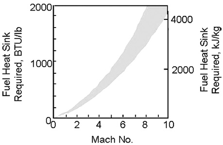
한편, Fig. 2에 보이는 Lander-Nixon 선도에 의하면[13,14], 극초음속 비행에 따른 냉각 소요량은 비행 마하수에 따라 급격하게 증가하여 마하 8로 비행하는 경우의 스크램제트 엔진은 약 3.5 MJ/kg에 달하는 냉각이 요구되는 것으로 추산되고 있다. 이에 따라, 스크램제트 연소실에 분사되기 위해 높은 압력으로 가압된 액체 탄화수소 항공유가 극초음속 비행체의 재생냉각시스템에서 냉매로 순환하게 되면 연료는 매우 높은 온도로 가열되고 결국 임계점(critical point)을 넘어 액체상과 기체상의 구분이 모호해지는 초임계(supercritical) 상태까지 도달하게 된다[15]. 뿐만 아니라 종류에 따라 특성의 차이가 있기는 하지만 탄화수소 항공유는 고온으로 가열시 많은 양의 열을 흡수하면서[14,16] 저탄소수 탄화수소로 열분해(thermal cracking or pyrolysis)되는 특성이 있는데[17,18], 이러한 탄화수소 항공유의 재생냉각시스템 내에서의 흡열분해 특성을 나타내는 파라미터는 흡열량, 전환율, 분해 생성물, 그리고 탄소 침적(coking) 경향 등으로 구분되며, 이에 대한 광범위한 연구동향은 이전연구[11]에서 분석을 수행한 바 있다.
이러한 열분해 특성과 비교하여 탄화수소 액체 항공유의 흡열 분해반응을 보다 효과적으로 달성하기 위한 다양한 방법들도 활발하게 연구되고 있는데, 그 중에서 대표적인 두 가지 방법은 촉매 분해(catalytic cracking)와 수증기 개질(steam reforming)이다. 특히, 촉매 분해는 특정 항공유에 적절한 촉매를 적용하면 열분해시보다 더 낮은 반응 온도에서도 더 많은 열을 흡수하면서 흡열반응이 발생하는 현상을 이용하는 기술이며[17,19], 수증기 개질은 탄화수소 항공유의 흡열분해 반응시 수증기를 첨가하면 흡열량 증가, 코킹 저감, 분해 생성물 중 수소 함량 증가 등과 같은 다양한 장점이 있음을 이용하는 방법이다[20,21]. 따라서 본 연구에서는 효과적인 흡열분해 특성 개선 및 성능 향상 방안으로 다양하게 시도되고 있는 탄화수소 항공유에 대한 촉매 분해와 수증기 개질에 관한 전세계적인 연구 동향을 분석하고 주요 연구 결과를 정리하였다.
3. 촉매 분해(Catalytic cracking)
탄화수소 항공유가 흡열분해 반응시 적절한 촉매를 사용하면 열분해시보다 훨씬 많은 열을 흡수하며 수소(H2)와 저분자량 탄화수소(CmHn) 로 분해될 수 있는데, MCH(Methylcyclohexane, C7H14)의 경우에는 백금(Pt) 촉매를 사용하면 톨루엔(toluene, C7H8)과 수소로 쉽게 분해되며, 규격화된 탄화수소 항공유들인 JP-7, JP-8, 그리고 JP-10의 경우에는 상용 제올라이트(zeolite)를 촉매로 이용하면 흡열반응을 촉진시키는데 효과가 있는 것으로 확인되었다[14,16,19,22,23]. 특히 제올라이트 촉매는 높은 활성, 형상 선택성(shape selectivity), 열 안정성, 양이온 교환 능력(cation exchange capability) 등이 있어 탄화수소의 촉매 분해에 널리 사용되고 있으며[24], 연료의 종류에 따라 니켈(Ni), 백금(Pt), 구리(Cu) 등 다양한 금속 계열의 촉매도 효과적인 것으로 알려져 있다[25-27]. 이러한 촉매를 이용한 연료의 흡열분해는 압력 및 온도와 같은 반응 조건 뿐만 아니라 촉매의 형태, 촉매의 고정매체(binding medium), 연료의 촉매층 통과 속도 및 체류 시간 (또는 공간속도(SV, space velocity)), 촉매 표면적 대 부피의 비(surface/volume ratio) 등 여러 가지 파라미터에 의해 결정된다[14,19, 22,23].
탄화수소 항공유의 촉매분해와 관련된 연구 중에서 중요한 이슈는 촉매를 이용하여 연료의 흡열량과 전환율을 극대화하는 방안 뿐만 아니라 촉매의 활성이 떨어지는 오염 또는 피독(poisoning)의 최소화 문제이다. 고온/고압 조건에서 연료가 분해되어 발생하는 탄소 성분이 촉매층에 침적되면 촉매가 더 이상 기능을 발휘할 수 없어 흡열량이 급격히 감소하기 때문에, 아직까지도 촉매분해와 촉매활성에 관련된 다양한 연구가 진행되고 있다. 특히 제올라이트는 가솔린에 대한 실험 결과에서 silica/alumina 촉매보다 코킹을 덜 발생시키는 것으로 확인되었고[14,28], Castaldi 등[29]은 JP-8과 JP-10 연료에 대한 촉매분해 실험에서 로듐(Rh) 촉매를 alumina monolith로 지지하여 hydrogenation 반응을 촉진하면 연료의 방향족(aromatics) 성분을 감소시켜 코킹의 주요 원인으로 지목되고 있는 PAH(Polycyclic Aromatic Hydrocarbons)에 의한 코킹 발생과 그에 따른 촉매의 피독을 억제할 수 있음을 제시하였다.
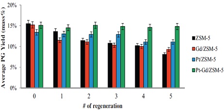
한편, 여러 연구들에서는 주 촉매에 대한 활성 촉진제로서 다양한 물질들을 첨가하여 활용하는 기술도 개발하였는데, 예를 들면 제올라이트를 주 촉매로 사용하는 경우 이리듐(Ir), 팔라듐(Pd), 백금(Pt), 로듐(Rh), 루비듐(Ru) 등과 같은 귀금속을 첨가하면 제올라이트 촉매의 코킹 저항성과 재생 능력이 증대될 뿐만 아니라, 탄화수소의 촉매 분해 활성이 증가하는 것으로 확인되었다[24]. 또한 니켈(Ni)을 주 촉매로 사용하는 경우에는 칼륨(K), 리튬(Li), 나트륨(Na), 마그네슘(Mg), 칼슘(Ca) 등과 같은 알칼라인 계열의 물질을 활성 촉진제로 첨가하면 금속 촉매와 지지체 사이의 상호 작용 특성을 변화시킴으로써 코킹을 감소시키는데, 특히 칼륨(K)과 나트륨(Na)은 고온에 노출된 탄화수소로부터 탄소가 생성될 때 촉매의 활성 산점에 침적되어 촉매를 오염시키는 비정형(amorphous) 탄소가 형성되는 대신 탄소 섬유의 형태로 형성되도록 유도함으로써 코킹으로 인한 니켈(Ni) 촉매의 활성 저하를 효과적으로 차단하는 것으로 보고되었다[26]. 이러한 사실을 바탕으로 최근 Kim 등[24]은 JP-8의 촉매 분해시 제올라이트 촉매에 백금(Pt)과 가돌리늄(Gd)을 활성 촉진제로 첨가하여 코킹 발생을 감소시키고 촉매의 재생 능력을 증대시켰을 뿐만 아니라 Fig. 3에 보이는 바와 같이 재생 촉매의 반복 사용시에도 촉매 분해에 의한 JP-8의 PG(Petroleum Gas)로의 전활율이 감소하지 않고 거의 일정하게 유지됨을 확인하였다. 이러한 촉매 활성 촉진 특성은 희토류 금속들(rare earth metals)도 보유하고 있으며, 특히 이들을 제올라이트에 첨가하면 제올라이트의 산점과 촉매 특성을 변화시켜 열안정성과 촉매 활성이 크게 증대되는 것으로 확인되었다[24].
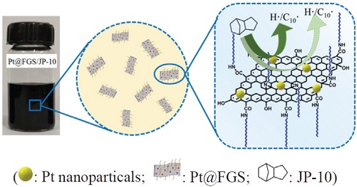
또한, 최근에는 촉매의 활성을 지속적으로 유지함과 동시에 연료의 열전달을 촉진함으로써 전체적인 흡열 특성을 향상시킬 수 있는 방안으로서 탄화수소 연료에 촉매 성분을 포함하는 나노입자를 혼합하여 그 효과를 확인하기 위한 연구들이 수행되었다[25,30]. 특히 초기 연구에서는 유기물로 코팅된 금속 촉매의 나노입자를 적용하였으나, 고온 조건에서는 코팅이 파괴되어 금속 입자들이 서로 결합함으로써 촉매의 접촉 표면적 감소와 그에 따른 촉매 기능의 저하 문제가 발견되었고, 이를 해결하기 위하여 제올라이트 계열의 비금속 촉매를 나노입자화하여 탄화수소 연료에 혼합하여 그 효과를 다각적으로 검증하는 연구가 진행되고 있다. 예를 들면 Sun 등[30]은 나노제올라이트가 포함된 JP-10을 이용한 초임계 조건에서의 튜브형 반응기 실험 결과로부터 순수한 JP-10을 적용한 경우에 비하여 같은 반응 조건에서 3배 이상의 전환율이 달성됨을 확인하였으며, Liu 등[25]은 현대의 대표적인 나노물질인 그래핀 구조(Functionalized Graphene Sheets, FGS)를 적용하여 액상의 JP-10 연료에 백금(Pt) 입자를 효과적으로 균일하게 분포시킴으로써(Fig. 4) 동일한 반응 조건에서 더욱 높은 흡열량과 분해성성물 중의 수소 비율을 달성하였을 뿐만 아니라(Fig. 5) 연료의 열전도도까지 상승시킴으로써 실제 반응기 내에서의 열전달을 포함한 흡열반응 특성을 더욱 향상시킬 수 있음을 배치 반응기 실험을 통해 확인하였다. 이상에서 논의한 탄화수소 항공유의 흡열 촉매 분해에 대한 주요 연구결과들을 Table 2에 요약하여 정리하였다.
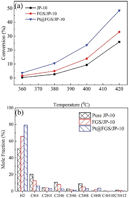
Conversion (a), and gaseous products (b) of JP-10 cracking with and without Pt and FGS(graphene) nanoparticles[25].
4. 수증기 개질(Steam reforming)
촉매를 이용한 연료 개질(catalytic reforming) 기술은 본래 화학공학에서 메탄과 메탄올 등 저분자량 탄화수소를 원료로 하여 수소와 암모니아를 생산하기 위해 개발된 기술로서[31,32], 지금은 현대 산업 전반에 걸쳐서 다양하게 활용되고 있다. 이 기술을 극초음속 비행체용 재생냉각시스템에 활용하는 것에 대한 최초의 아이디어는 러시아의 극초음속 비행체 개발 프로그램에서 Gurijanov and Harsha[33]가 탄화수소를 연료로 사용하는 스크램제트 엔진의 열역학적 사이클 성능을 향상시키기 위하여 도입한 Ajax 비행체 개념에 적용한 것으로서, 그 후 Korabelnikov and Kuranov[20,21]가 탄화수소 액체연료의 열분해시 catalytic steam reforming을 추가하면 흡열성능 향상과 분해 생성물 중의 높은 수소 비율을 획득할 수 있음을 확인하여 주목을 받았다. 그로부터 미국과 중국에서의 다양한 관련 연구를 통하여 steam reforming은 우수한 흡열반응 특성이 있을 뿐만 아니라 코킹 발생도 억제하는 것으로 확인되어, 스크램제트 엔진에서의 탄화수소 흡열연료를 효과적으로 이용할 수 있는 방법 중 하나로서 지속적으로 연구되고 있다[14,21,25,26,30,34].
Korabelnikov and Kuranov[21]에 의하면 steam reforming은 2단계에 걸쳐 진행되는데, 예비반응 성격의 첫 번째 단계에서는 상대적으로 낮은 온도인 300∼400°C에서 액체 탄화수소가 steam과 반응하여 CH4와 CO2로 1차 분해되고, 본 반응인 두 번째 단계에서는 700∼900°C의 고온 조건에서 CH4가 다시 steam과 반응하여 H2와 CO로 2차 분해된다. 이때 첫 번째 반응은 열적으로 중립 반응인데 비하여 두 번째 반응이 강력한 흡열반응이므로, steam reforming에 의한 흡열량은 액체 수소를 이용하는 경우의 냉각량에 버금갈 정도로 상당할 뿐만 아니라 H2 생성 비율이 부피 기준으로 70%에 달하고, 최종 분해 생성물인 H2와 CO 혼합물의 발열량도 CH4보다 25% 이상 향상되는 것으로 확인되었으며, 또한 steam이 반응 과정에서 발생하는 coke와 결합하여 CO와 H2로 변환되므로 코킹 발생도 효과적으로 억제하는 것으로 분석되었다[14,21]. 그 후 중국의 여러 연구그룹에서 중국에서 가장 널리 사용되고 있는 탄화수소 항공유 RP-3를 대상으로 관련 연구들을 활발하게 진행한 결과[31,35, 36], steam reforming은 니켈 계열의 개질용 촉매를 반응기 표면에 약 0.2 mm 두께로 얇게 도포하는 것만으로도 충분히 효과가 발생하며, 수분 함량 비율에 따라 달라지기는 하지만 전반적으로 열분해 대비 높은 흡열량, 분해 생성물 중 높은 수소 비율, 낮은 코킹 발생, 500°C 이하의 비교적 낮은 온도에서도 활발한 반응 특성이 있음이 확인되었다[31,35].
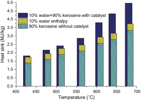
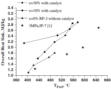
Fig. 6에는 반응 압력 3 MPa 조건에서 수분이 10% 포함되었을 때의 반응 온도에 따른 총 흡열량 비교 결과가 도시되어 있는데, catalytic steam reforming에 의한 총 흡열량이 연료와 물 자체의 흡열량 보다도 훨씬 크게 측정되었으며 이러한 경향은 반응 온도가 높아질수록 더욱 두드러지게 나타나고 있다[35]. 또한 Fig. 7에는 반응압력 3 MPa에서 RP-3 연료의 수분 함량 변화에 따른 총 흡열량을 비교한 결과가 나와 있는데, RP-3가 열분해될 때의 흡열량에 비하여 catalytic steam reforming에 의한 흡열량이 월등히 크게 나타남을 보여주고 있다. 뿐만 아니라 500°C 이하의 비교적 낮은 온도에서는 수분 함량이 많을수록 총 흡열량이 크지만 약 550°C 이상의 온도에서는 수분 함량이 10%만 되어도 steam reforming의 효과가 충분히 발휘되고 있음을 알 수 있다[31]. 참고로 Fig. 7에는 전용 흡열 연료인 JP-7에 대하여 같은 압력 조건에서의 흡열량 비교 결과도 함께 도시되어 있으며, RP-3의 기본적인 흡열량이 JP-7 연료와 매우 유사함을 알 수 있다.
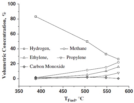
Fig. 8에는 385∼575℃의 비교적 낮은 온도 범위에서 반응압력 3 MPa 조건에서 수분함량이 30%일 때의 반응온도에 따른 분해생성물 비교를 도시하였는데, 가장 두드러진 특징은 steam reforming에 의하여 수소가 가장 많이 생성되고 있다는 사실이다. Fig. 8에 의하면 온도가 증가함에 따라 수소 생성 비율이 서서히 감소하는 경향이 있기는 하지만, catalytic steam reforming을 이용하면 재생냉각시스템 내부에서의 흡열량 증대와 코킹 감소 효과를 얻을 수 있을 뿐만 아니라 재생냉각시스템을 통과하면서 흡열분해된 연료가 스크램제트 엔진의 초음속 연소실에서 공기와 혼합/연소되는 특성도 크게 향상되므로, 이는 탄화수소의 수증기 개질이 스크램제트 엔진의 전체적인 사이클 효율과 추진 성능 관점에서도 매우 유리하게 작용함을 의미하는 상당히 중요한 결과이다.
한편, 이러한 탄화수소 항공유에서의 catalytic steam reforming은 압력과 온도가 증가할수록 열분해(thermal cracking) 반응이 크게 활성화되면서 두 반응이 상호 경쟁하는 현상이 발생하여, 상대적으로 steam reforming에 의한 흡열량 증가와 코킹 억제 효과가 감소하는 경향이 나타나는 것으로 확인되어[31,36], 수증기 개질 기술을 실제로 능동냉각시스템에 적용시에는 냉각 성능과 코킹 측면에서 가장 효율적인 최적의 반응 조건에서 운용되도록 설계하는 것이 매우 중요하다. 이상에서 논의한 수증기 개질을 이용한 탄화수소 항공유의 흡열 성능 향상 방안에 대한 주요 연구결과들을 Table 3에 정리하였다.
5. 요약 및 결론
본 연구에서는 극초음속 비행체용 재생냉각시스템 개발을 위한 체계적인 연구의 시작 단계로서 탄화수소 액체연료의 흡열반응 성능을 향상시키기 위해 시도되고 있는 다양한 연구들에 대하여 현재까지의 연구동향을 포함한 세부기술 분석을 수행하였다. 일반적으로 탄화수소 항공유는 고온으로 가열시 열을 흡수하면서 저분자량 탄화수소로 분해되는데, 이러한 열분해 특성과 비교하여 탄화수소 액체 항공유의 흡열 분해반응을 보다 효과적으로 달성하기 위한 다양한 방법들 중에서 촉매 분해(catalytic cracking)와 수증기 개질(steam reforming)이 대표적이다. 특히, 촉매 분해는 특정 항공유에 제올라이트 또는 금속 등의 적절한 촉매를 적용하면 열분해될 때보다 더 낮은 반응 온도에서도 더 많은 열을 흡수하는 흡열반응이 발생하는 현상이며, 수증기 개질은 탄화수소 항공유의 흡열분해 반응시 수증기를 첨가하여 흡열량을 증가시킴과 동시에 코킹을 저감시키고 분해 생성물 중 수소 함량을 높임으로써 스크램제트 엔진에서 효과적인 연소가 가능한 장점이 있다. 따라서 본 연구 결과를 토대로 현재 국내에서 사용하고 있는 탄화수소 항공유에 최적화된 촉매 분해와 수증기 개질 기술을 개발함으로써, 향후 한국형 극초음속 순항 비행체에 탑재 가능한 효율적이고 안정적인 능동재생냉각시스템 개발에 활용할 수 있을 것으로 기대된다.
Acknowledgments
이 연구는 부경대학교 자율창의학술연구비(2020년)에 의하여 수행되었습니다.
References
- Van Wie, D.M., D’Alessio, S.M., and White M.E., “Hypersonic Air-breathing Propulsion,“ Johns Hopkins APL Technology Digest, Vol. 26, No. 4, pp. 430-437, 2005.
- https://news.joins.com/article/22878621
-
Tang, M. and Chase, R.L., “The quest for hypersonic flight with air-breathing propulsion,” 15th AIAA International Space Planes and Hypersonic Systems and Technologies Conference, AIAA 2008-2546, 2008.
[https://doi.org/10.2514/6.2008-2546]

- National Research Council, Review and Evaluation of the Air Force Hypersonic Technology Program, National Academy Press, Washington D.C., pp. 5-17, 1998.
- Pace, D., “Scramjet Fuel Choices: Hydrogen versus Hydrocarbons,” Journal of University of New South Wales at ADFA, Vol. 1, pp. 1-12, 2007.
-
Sobel, D.R. and Spadaccini, L.J., “Hydrocarbon fuel cooling technologies for advanced propulsion,” ASME Journal of Engineering for Gas Turbines and Power, Vol. 119, No. 2, pp. 344-351, 1997.
[https://doi.org/10.1115/1.2815581]

-
Edwards, T., “Liquid fuels and propellants for aerospace propulsion: 1903-2003,” Journal of Propulsion and Power, Vol. 19, No. 6, pp. 1089-1107, 2003.
[https://doi.org/10.2514/2.6946]

-
Choi, H., Lee, H.J., and Hwnag, K., “Research activities about characteristics of fuel injection and combustion using endothermic fuel,” Journal of the Korean Society of Propulsion Engineers, Vol. 17, No. 4, pp. 73-80, 2013.
[https://doi.org/10.6108/KSPE.2013.17.4.073]

-
Boudreau, A.H., “Hypersonic air-breathing propulsion efforts in the Air Force Research Laboratory,” 13th AIAA/CIRA International Space Planes and Hypersonic Systems and Technologies Conference, AIAA 2005-3255, 2005.
[https://doi.org/10.2514/6.2005-3255]

-
Zhong, Z., Wang, Z., and Sun, M., “Effects of fuel cracking on combustion characteristics of a supersonic model combustor,” Acta Astronautica, Vol. 110, pp. 1-8, 2015.
[https://doi.org/10.1016/j.actaastro.2015.01.003]

- Lee, H.J., “Technical analysis of thermal decomposition characteristics of liquid hydrocarbon fuels for a regenerative cooling system of hypersonic vehicles,” Journal of Aerospace System Engineering, Vol. 14, No. 4, pp. 32-39, 2020.
- Coordinating Research Council, Handbook of Aviation Fuel Properties, 3rd ed., CRC Report No. 635, 2004.
-
Lander, H. and Nixon, A.C., “Endothermic fuels for hypersonic vehicles,” Journal of Aircraft, Vol. 8, No. 4, pp. 200-207, 1971.
[https://doi.org/10.2514/3.44255]

-
Edwards, T., “Cracking and deposition behavior of supercritical hydrocarbon aviation fuels,” Combustion Science and Technology, Vol. 178, pp. 307-334, 2006.
[https://doi.org/10.1080/00102200500294346]

-
Edwards, T., “USAF Supercritical hydrocarbon fuels interest,” 31st AIAA Aerospace Sciences Meeting, AIAA 93-0807, January 1993.
[https://doi.org/10.2514/6.1993-807]

-
Huang, H., Sobel, D.R., and Spadaccini, L.J., “Endothemic heat-sink of hydrocarbon fuels for scramjet cooling,” 38th AIAA/ ASME/SAE/ASEE Joint Propulsion Conference & Exhibit, AIAA 2002-3871, July, 2002.
[https://doi.org/10.2514/6.2002-3871]

- Cooper, M. and Shepherd, J.E., “Thermal and Catalytic Cracking of Fuel for Pulse Detonation Engine Applications,” GALCIT Report FM 2002.002, 2002.
-
Rao, P.N. and Kunzru, D., “Thermal cracking of JP-10: Kinetics and product distribution,” Journal of Analytical and Applied Pyrolysis, Vol. 76, No. 1-2, pp. 154-160, 2006.
[https://doi.org/10.1016/j.jaap.2005.10.003]

-
Kim, J., Hyeon, D.H., Park, S.H., Chun, B.H., Jeong, B.H., Han, J.S. and Kim, S.H., “Catalytic endothermic reactions of exo-tetrahydrodicyclopentadiene with zeolites and improvement of heat of reactions,” Catalysis Today, Vol. 232, pp. 63-68, 2014.
[https://doi.org/10.1016/j.cattod.2013.10.045]

-
Korabelnikov, A.V. and Kuranov, A.L., “Thermochemical conversion of hydrocarbon fuel under the concept ‘AJAX’,” 9th AIAA International Space Planes and Hypersonic Systems and Technologies Conference, AIAA 99-4921, 1999.
[https://doi.org/10.2514/6.1999-4921]

-
Korabelnikov, A.V. and Kuranov, A.L., “Hypersonic flight vehicle heat protection using chemical heat regeneration,” 40th AIAA Aerospace Sciences Meeting & Exhibit, AIAA 2002-0913, 2002.
[https://doi.org/10.2514/6.2002-913]

-
Huang, H., Spadaccini, L.J., and Sobel, D.R., “Fuel-cooled thermal management for advanced aeroengines,” ASME Journal of Engineering for Gas Turbines and Power, Vol. 126, No. 2, pp. 284-293, 2004.
[https://doi.org/10.1115/1.1689361]

-
Kim, S., Sasmaz, E., Pogaku, R., and Lauterbach, J., “Effects of reaction conditions and organic sulfur compounds on coke formation and HZSM-5 catalyst performance during jet propellant fuel (JP-8) cracking,” Fuel, Vol. 259, 116240, 2020.
[https://doi.org/10.1016/j.fuel.2019.116240]

-
Kim, S., Sasmaz, E., and Lauterbach, J., “Effect of Pt and Gd on coke formation and regeneration during JP-8 cracking over ZSM-5 catalysts,” Applied Catalysis B: Environmental, Vol. 168-169, pp. 212-219, 2015.
[https://doi.org/10.1016/j.apcatb.2014.12.027]

-
Liu, G., Jia, X., Tian, Y., Gong, S., Wang, L., and Zhang, X., “Preparation and remarkable catalytic cracking performances of Pt@FGS/JP-10 nanofluids,” Fuel, Vol. 252, pp. 228-237, 2019.
[https://doi.org/10.1016/j.fuel.2019.04.119]

-
Zhang, H., Xiao, Z., Yang, M., Tian, Y., Li, G., Zhang, X., and Liu, G., “Catalytic steam reforming of JP-10 over Ni/SBA-15,” International Journal of Hydrogen Energy, Vol. 45, pp. 4284-4296, 2020.
[https://doi.org/10.1016/j.ijhydene.2019.12.049]

-
Wang, Y., Hong, Z., and Mei, D., “A thermally autonomous methanol steam reforming microreactor with porous copper foam as catalyst support for hydrogen production,” International Journal of Hydrogen Energy, Vol. 46, pp. 6734-6744, 2021.
[https://doi.org/10.1016/j.ijhydene.2020.11.111]

- Schobert, H.H., The Chemistry of Hydrocarbon Fuels, Butterworths, London, 1990.
-
Castaldi, M.J., Leylegian, J.C., Chinitz, W., and Modroukas, D.P., “Development of an effective endothermic fuel platform for regeneratively-cooled hypersonic vehicles,” 42nd AIAA/ASME/SAE/ASEE Joint Propulsion Conference & Exhibit, AIAA 2006-4403, July, 2006.
[https://doi.org/10.2514/6.2006-4403]

-
Sun, W., Liu, G., Wang, L., and Zhang, X., “Quasi-homogeneous catalytic cracking of JP-10 over high hydrocarbon dispersible nanozeolites,” Fuel, Vol. 144, pp. 96-102, 2015.
[https://doi.org/10.1016/j.fuel.2014.12.022]

-
Hou, L., Jia, Z., Gong, J., Zhou, Y., and Piao, Y., “Heat sink and conversion of catalytic steam reforming for hydrocarbon fuel,” Journal of Propulsion and Power, Vol. 28, No. 3, pp. 453-457, 2012.
[https://doi.org/10.2514/1.B34315]

- Wang, Y.H., Wu, D.Y., and Chi, J., “The status and current development of hydrogen energy and its application technology,” Chemical Engineering Progress, Vol. 20, pp. 6-8, 2001.
-
Gurijanov, E.P. and Harsha, P.T., “AJAX: new directions in hypersonic technology,” 6th AIAA International Space Planes and Hypersonic Systems and Technologies Conference, AIAA 96-4609, 1996.
[https://doi.org/10.2514/6.1996-4609]

-
Liu, S., Feng, Y., Cao, Y., Gong, K., Zhou, W., and Bao, W., “Numerical simulation of supercritical catalytic steam reforming of aviation kerosene coupling with coking and heat transfer in mini-channel,” International Journal of Thermal Sciences, Vol. 137, pp. 199-214, 2019.
[https://doi.org/10.1016/j.ijthermalsci.2018.10.039]

-
Hou, L., Dong, N., Ren, Z.-Y., Zhang, B., and Hu, S.-L., “Cooling and coke deposition of hydrocarbon fuel with catalytic steam reforming,” Fuel Processing Technology, Vol. 128, pp. 128-133, 2014.
[https://doi.org/10.1016/j.fuproc.2014.07.011]

-
Feng, Y., Liu, Y., Cao, Y., Gong, K., Liu, S., and Qin, J., “Thermal management evaluation for advanced aero-engines using catalytic steam reforming of hydrocarbon fuels,” Energy, Vol. 193, 116738, 2020.
[https://doi.org/10.1016/j.energy.2019.116738]

