Heat Flux Measurements in High Velocity Oxygen-Fuel Torch Flow for Testing High Thermal Materials
Copyright Ⓒ The Korean Society of Propulsion Engineers
This is an Open-Access article distributed under the terms of the Creative Commons Attribution Non-Commercial License(http://creativecommons.org/licenses/by-nc/3.0) which permits unrestricted non-commercial use, distribution, and reproduction in any medium, provided the original work is properly cited.
Abstract
A commercial HVOF torch (originally designed for coating applications) has been modified as a high temperature flow source for material testing. In this study, a water cooled commercial Gardon gauge was used to measure heat fluxes at four locations away from the nozzle exit. The cooling water temperature data were used to calculate calorimetric heat fluxes at the same locations. The heat fluxes from both methods were compared and the calorimetric heat fluxes were found to be many times higher than the Gardon gauge heat fluxes. A hypothesis is applied to the calorimetric method to understand the discrepancy seen between the methods. The Gardon gauge heat fluxes are seen to be in the range of the hypothesized calorimetric calculations. This can be considered as a considerable validation for the hypothesis, but further refinement needed using appropriate numerical models.
초록
상업용 HVOF 토치 (원래 코팅 용도로 설계됨)가 재료 테스트를 위한 고온 유동원으로 수정되었다. 이 연구에서는 수냉식 상용 Gardon 게이지를 사용하여 노즐 출구에서 떨어진 네 위치에서 열유속을 측정하였다. 냉각수 온도 데이터는 동일한 위치에서 열량 측정 열유속 (calorimetric heat flux)을 계산하는 데 사용되었다. 두 방법의 열유속을 비교 한 결과 열량 측정 열유속이 Gardon 게이지 열유속보다 몇 배 더 높은 것으로 나타났다. 두 가지 방법 사이에 나타나는 불일치를 이해하기 위해 열량 측정 방법에 대한 가설을 적용하였다. 이것은 가설에 대한 상당한 검증으로 간주될 수 있지만 적절한 수치 모델을 사용하여 추가 개선이 필요하다.
Keywords:
HVOF, Gardon Gauge, Calorimetric Heat Flux, Material Testing키워드:
고속산소-연료화염, 가든 게이지, 열량 열유속, 재료 시험1. Introduction
Carbon-Carbon (C/C) composites and ultra-high temperature ceramics (UHTCs) are used in extreme thermal environments, especially during atmospheric entry or re-entry in spacecraft thermal protection systems. Many UHTCs have melting points above 3000 K[1]. It is very important to study these materials at extreme thermal conditions using ground testing equipment in order to understand their endurance, thermo-mechanical properties, and other characteristics.
The candidate materials are tested/evaluated using arc-jet plasma wind tunnels, inductively coupled plasma (ICP) plasmatrons and combustion torches like oxyacetylene, high velocity oxygen fuel torch, etc. The operating principle of each type of ground testing equipment is different from each other.
In arc jet plasma wind tunnel, working gas (air for earth, CO2 for mars) is allowed to pass through an electric arc generated between the electrodes. The direct energy transfer from the electric arc to the working gas causes dissociation and ionization to form high thermal plasma[2].
In ICP plasmatron, an electric coil induces electromagnetic fields inside the working gas. The induced electromagnetic field heats up the working gas and causes dissociation and ionization to form high thermal plasma[3].
In combustion torches, the test flow consists of combustion product gases instead of plasma. The combustion torches are inexpensive and easy to operate than the plasma wind tunnels (both arc-jets and plasmatrons). The combustion torches can be used for primary studies of the candidate materials prior to further investigation using plasma wind tunnels which are more complex but closer to real flow conditions. The fuel used in combustion torches usually include acetylene, propane, and butane [4-6]. One type of combustion torch that can be used for material testing is HVOF torch. Originally designed as thermal spraying equipment for coating powders on a target substrate. Without the supply of coating powder, the HVOF torch act as a source of high velocity and high temperature flow.
The HVOF torch at Jeonbuk National University’s (JBNU) High Enthalpy Plasma Research Center (HEPRC) produces test flows at the temperatures above 2000 K. A recent study[7] estimated the Mach number of the flow generated by HEPRC’s HVOF torch as ≈1.4 upto 100 mm away from the nozzle exit using wedge probe technique.
The objective of this paper is to measure the cold wall stagnation point heat flux of the HVOF flow using a water cooled Gardon gauge at four locations (120 mm, 140 mm, 160 mm, and 180 mm) away from the nozzle exit and to compare with the heat flux results calculated using calorimetric data (cooling water in and out temperatures). The experimental locations were chosen in the subsonic region of the flow, in order to avoid any unforeseeable damage to the newly procured Gardon gauge, that may occur in the supersonic region. The measurement method may be seen as simple, but it is crucial for understanding the flow parameters which will result in a better interpretation of material testing results. The cold wall stagnation point heat flux is important for numerical simulations which can be used to deduce other flow parameters[8], and for cross-verification of material testing results from other testing equipment like plasma wind tunnels. Since the primary application of an HVOF system is material coating, no published research work was found regarding measurement of heat flux in an HVOF system using Gardon gauge method or calorimetric method. Apart from development of UHTCs for aerospace applications, understanding HVOF system flow will also help in the development of efficient coating processes.
2. Experiment
2.1 HVOF torch
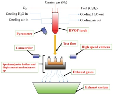
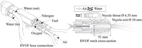
The HVOF torch used for this study is an air and water-cooled Oerlikon Metco DJ9W gun HVOF torch with a nozzle exit diameter of 10 mm and a throat diameter of 6.35 mm. The dual cooling allows the torch to operate at temperatures higher than typical air cooled torches. The torch is balanced on a tripod which enables proper alignment of test flow with specimens or probes. The heat flux measuring Gardon gauge is mounted on the displacement mechanism which is remotely controlled using a computer. Using the displacement mechanism, the probe is placed in and out of the test flow.
The probe displacement mechanism is water cooled. Flow rate, pressure, and temperature of the cooling water is monitored using respective sensors during the experiments.
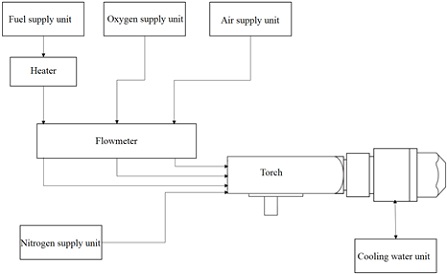
During the heat flux measurement experiments, the fuel and oxygen (oxidizer) were supplied to the torch from external tanks via hoses. The fuel used was liquefied propane, which was converted into gas using a heater before being fed into the torch. To obtain a stable test flow, nitrogen was used as a stabilizing or carrier gas which was also fed from external tanks. The fuel and oxygen ratio were controlled and monitored using flow meters.
2.2 Gardon gauge
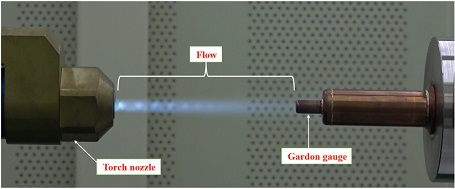
A Gardon gauge from Medtherm Co., USA was used for heat flux measurements. Gardon gauges are also called as circular foil type heat flux sensors or asymptotic calorimeters. The main part of the sensor is a thin circular constantan foil placed over a copper annulus. The copper annulus is water cooled and act as a heat sink. One copper wire is attached to the foil and other copper wire is attached to the copper annulus. Two copper wires are combined to form a differential thermocouple which generates voltage signal proportional to the heat flux. Gardon gauge was invented by Robert Gardon in 1953[9].
The Gardon gauge manufacturer calibrated the gauge and provided the voltage to heat flux conversion chart. The shape of the Gardon gauge is cylindrical has a diameter of∼9.5 mm. The total length of the gauge is∼20 mm, out of which∼2 mm is attached inside the probe displacement mechanism.
During the experiments, the cooling water to the Gardon gauge sensor and the probe displacement mechanism was supplied by a chiller at a temperature of∼15℃. The flow rate of cooling water to the Gardon gauge sensor was measured using a flowmeter and the temperatures of cooling water in and out of the gauge were measured using two K-type thermocouples respectively. Cooling water flow rates and cooling water temperature difference were used to calculate the heat flux using calorimetric principle and compared with Gardon gauge heat flux.
3. Results and discussion
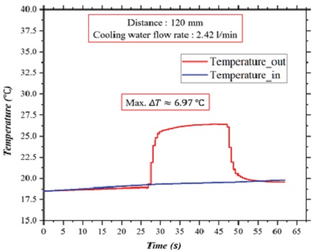
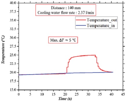
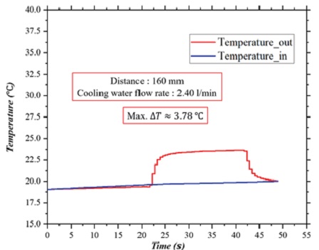
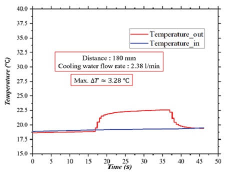
Figs. 5-8 show the gauge cooling water in and out temperatures.
The experiments were carried out for 20 s at each location. The cooling water flow rate was in range of 2.37 to 2.42 litres/min. The gas input parameters are given in table 1.
The cooling water temperature data show that ∆T (difference between the in and out water temperatures) increases as the distance between the nozzle and sampling location decreases.
Figs. 5-8 show that cooling water temperatures (both in and out temperatures) increased steadily in pre-exposure sections with identical slopes and ΔT≈0. The reason for this steady increase is that the operation of the HVOF torch increases the ambient temperature. The similar trend also can be seen in post-exposure sections (identical slopes and ΔT≈0). In both the sections (.i.e. when the probe is not exposed to the flow), the net heat transfer to the probe due to ambient conditions is zero, since ΔT≈0.
Also, during the exposure of the probe to flow, the slopes of water in and out temperature curves are almost identical to pre-exposure/post-exposure sections and also to each other (except during the steep increase and decrease occurred at the instants when the probe moved in and out of the flow respectively).
In other words, the steady incremental slopes seen throughout cooling water temperature curves are due to rise in the ambient temperature caused by heating of the surrounding air, specimen holder, and displacement mechanism (external factors) and can be neglected. The ΔT experienced by the probe during the exposure is only due to the heat transfer from the flow, not from other external factors.
The calorimetric heat flux () was calculated using equation 1.
| (1) |
Where, is cooling water mass flow rate, Cp is the specific heat at constant pressure of water and d is the diameter of the gauge (i.e the surface perpendicular to the flow).
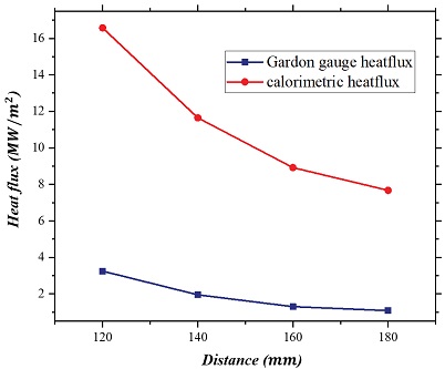
Fig. 9 shows comparison between Gardon gauge heat flux and heat flux calculated using equation 1 at four measuring locations.
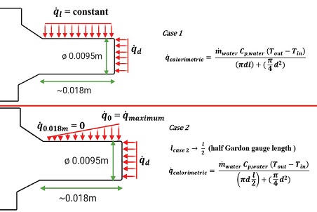
When computed using the standard calorimetric equation (equation 1), the calorimetric results are not in agreement with Gardon gauge results. The standard calorimeter equation results are seemed to be very high considering the HVOF system operating conditions and HEPRC’s working experience with a 0.4 MW arc-jet plasma wind tunnel. Since equation 1 is an ideal equation, which considers only the heat transfer at the surface area perpendicular to flow, a new hypothesis is proposed to include the probe’s (Gardon gauge) lengthwise heat transfer in the calorimetric heat flux calculations. The reason behind this hypothesis is the probe’s small size (magnitude in mm) and probe length (l) is almost twice the probe diameter (d), so there must be a considerable calorimetric heat transfer along the probe’s length (lengthwise heat addition to the probe’s cooling water).
This hypothesis assumes two cases to accommodate the length wise heat transfer in equation 1.
Case 1 assumption: the heat transfer is constant along the probe length, then the equation 1 can be written as,
| (2) |
Where πdl is the cylindrical surface area of the probe.
Case 2: the heat transfer is maximum at the start of the probe length and zero at the end of the probe length. In this case, if lengthwise average taken, then the effective length for case 2 becomes half of the case 1 length, i.e. . The calorimetric heat flux () for case 2 can be written as,
| (3) |
The assumed cases 1 and 2 should be considered as the limits and in theory the actual calorimetric heat flux value must be within these limits.
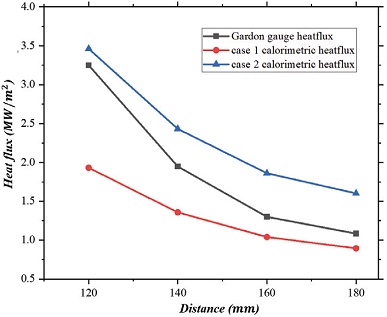
Fig. 11 compares the calculations from equations 2 and 3 with Gardon gauge heat flux.
Fig. 11 also shows that the Gardon gauge heat flux curve lies between two assumed (hypothesised) calorimetric curves. Even though Fig. 11 provides a considerable validation to the discussed hypothesis, the equations used for this assumption are simple and further refinements are needed to the assumed equations.
Also in Fig. 11, it can be seen that at locations 120 mm and 140 mm (near to the nozzle exit), the Gardon gauge heat flux values are closer to the upper limit of the assumed hypothesis and on the contrary, at locations 160 mm and 180 mm (far from the nozzle exit), the Gardon gauge heat flux values are closer to the lower limit of the assumed hypothesis. This may be due to the effects of the thermal boundary layer.
The thermal boundary layer thickness is inversely proportional to the flow velocity. So the locations near to the nozzle exit have thinner thermal boundary layers because of higher velocities compared to downstream and because of that, these locations have smaller distances between the free stream temperature and the probe wall temperature. Since [10], locations near to the nozzle will have heat fluxes closer to the hypothetical upper limit than the locations downstream.
In other words, the upper limit of the assumed hypothesis can be considered as to represent the minimum boundary layer thickness condition and the lower limit of hypothesis as to represent the maximum boundary layer thickness condition.
Both Gardon gauge and calorimetric methods are well established methods for measuring heat flux in a flow. The basic idea behind this research work was to compare/validate results using two methods simultaneously. The methods can be said to validate each other if they are in agreement. Though methods were simple, the results were important for the conversion of the HVOF system as a complete testing equipment for high temperature materials in comparison with plasma wind tunnels. In case of calorimetric methods, the components are simple (two k-type thermocouples and a flow meter) but in case of Gardon gauge, it is complex and expensive considering the small flow diameter, high velocities and high temperatures. Extreme caution was taken during experiments not to damage the Gardon gauge.
Though a considerable agreement is reached between the methods after applying the proposed hypothesis, yet the accuracy of this agreement is unknown at this moment. The further refinement of this hypothesis and validation of experimental results can be done using appropriate numerical codes which should incorporate boundary layer theory and various heat transfer models.
The future works will focus on refinement of the assumed hypothesis using a numerical model which will help to understand heat transfer from the flow to the probe surface better, and further development of HVOF system as an in-expensive and full-fledged testing equipment for high temperature materials with necessary intrusive and non-intrusive diagnostic tools.
4. Conclusion
A water cooled Gardon gauge was used to measure heat flux in flow generated by an HVOF system at four different locations, i.e. 120 mm, 140 mm, 160 mm, and 180 mm away from the nozzle exit. The calorimetric heat flux was computed based on the cooling water temperatures of the Gardon gauge which showed a huge discrepancy. A hypothesis is introduced to resolve the disagreement between two heat flux measurement methods used in this study. A considerable validation/agreement seen between the Gardon gauge results and hypothesised calorimetric heat flux results. The proposed hypothesis requires further validations using an appropriate numerical model and other flow diagnostic methods.
Acknowledgments
[이 논문은 한국추진공학회 2020년도 춘계학술대회(2020. 7. 16-17), 온라인 학술대회) 발표논문을 심사하여 수정ㆍ보완한 것임.]
This research was supported by Korea Basic Science Institute (National Research Facilities and Equipment Center) grant funded by the Ministry of Education (2019R1A6C1030013).
References
-
Fahrenholtz WG, and Hilmas, G. E. (2017) Ultra-High Temperature Ceramics: Materials for Extreme Environments. Scripta Materialia 129:94-99
[https://doi.org/10.1016/j.scriptamat.2016.10.018]

-
Chinnaraj RK, Oh PY, Shin ES, Hong BG, Choi SM (2019) Mach Number Determination in a High-Enthalpy Supersonic Arc-Heated Plasma Wind Tunnel. International Journal of Aeronautical and Space Sciences 20 (1):70-79.
[https://doi.org/10.1007/s42405-018-0128-x]

- Bottin B, Chazot, O., et. al. (October 1999) The VKI Plasmatron Characteristics and Performance. In: RTO AVT Course on Measurement Techniques for High Enthalpy and Plasma Flows, RTO EN-8. Rhode-Saint-Gen`ese, Belgium, pp. 6-01 - 06-26
-
Pienti L, Sciti D, Silvestroni L, Cecere A, Savino R (2015) Ablation tests on HfC- and TaC-based ceramics for aeropropulsive applications. Journal of the European Ceramic Society 35 (5):1401-1411.
[https://doi.org/10.1016/j.jeurceramsoc.2014.11.018]

-
Xiang L, Cheng L, Fan X, Shi L, Yin X, Zhang L (2015) Effect of interlayer on the ablation properties of laminated HfC–SiC ceramics under oxyacetylene torch. Corrosion Science 93:172-179.
[https://doi.org/10.1016/j.corsci.2015.01.021]

-
Wang Y-l, Xiong X, Zhao X-j, Li G-d, Chen Z-k, Sun W (2012) Structural evolution and ablation mechanism of a hafnium carbide coating on a C/C composite in an oxyacetylene torch environment. Corrosion Science 61:156-161.
[https://doi.org/10.1016/j.corsci.2012.04.033]

-
Chinnaraj RK, Jang HS, Oh PY, Hong SM, Choi SM (2020) Flow Characteristics of High Velocity Oxygen Fuel Torch. Journal of The Korean Society Combustion 25 (1):12-18.
[https://doi.org/10.15231/jksc.2020.25.1.012]

-
Chinnaraj RK, Hong SM, Kim HS, Oh PY, Choi SM (2020), Ablation Experiments of Ultra-High-Temperature Ceramic Coating on Carbon–Carbon Composite Using ICP Plasma Wind Tunnel, International Journal of Aeronautical and Space Sciences, 21(4), 889-905.
[https://doi.org/10.1007/s42405-020-00267-6]

-
Gardon R. (1953) An Instrument for the Direct Measurement of Intense Thermal Radiation. Review of Scientific Instruments 24 (5):366-370.
[https://doi.org/10.1063/1.1770712]

-
Schlichting H., and Gersten, K. (2017) Boundary-Layer Theory. 9 edn. Springer-Verlag, Berlin Heidelberg, p. 212.
[https://doi.org/10.1007/978-3-662-52919-5]

