Performance Assessment of the Dual-Throat Nozzle Thrust Vector Control in a 3D Rectangular Nozzle
Copyright Ⓒ The Korean Society of Propulsion Engineers
This is an Open-Access article distributed under the terms of the Creative Commons Attribution Non-Commercial License(http://creativecommons.org/licenses/by-nc/3.0) which permits unrestricted non-commercial use, distribution, and reproduction in any medium, provided the original work is properly cited.
Abstract
The dual-throat nozzle is an extremely effective method in the thrust vectoring control field, utilizing another convergent section to connect with the divergent part of the conventional convergent-divergent nozzle. In the present research, the numerical simulation is conducted to investigate the effects of the injection angle on thrust vectoring performance in a 3D supersonic nozzle. Five injection angles are discussed and core performance variations are analyzed, including the deflection angle, injected mass flow ratio, system resultant thrust ratio, efficiency, Mach number contour and streamline on the symmetry plane, and Mach number contours at different slices. Meaningful conclusions are offered for fighter jet designers.
초록
이중목 노즐은 유체 추력벡터제어 분야에서 특히 효과적인 방법이며, 다른 축소부가 종래의 축소-확대 노즐의 확대부에 연결된다. 본 연구에서는 3차원 초음속 직사각형 노즐에서 추력벡터제어 성능에 대한 분사각의 영향을 조사하기 위하여 수치해석을 수행하였다. 5개의 분사각에 대하여 다루었으며, 편향각도, 분사 질량유량비, 시스템 전체 추력비, 전체 피칭 추력효율, 대칭면에서의 마하수 분포와 유선 및 다른 면에서 마하수 분포를 포함하는 임계 성능변화가 정량적으로 그리고 정성적으로 분석되었다. 본 연구의 결과는 특히 전투기 설계자에게 유용한 기술적 자료를 제공한다.
Keywords:
Three-dimensional, Thrust vectoring control, Compressible flow, Dual-throat nozzle키워드:
3차원, 추력벡터제어, 압축성 유동, 이중목 노즐1. Introduction
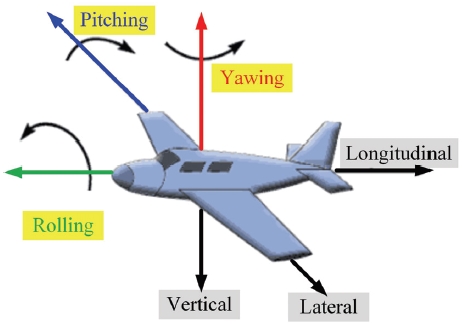
Thrust vectoring control (TVC) is an useful technique that has been utilized in various air vehicles. TVC can not only change the line of thrust, but also pitch, yaw, and roll the aircraft, as presented in Fig. 1.
In general, there are two types of TVC that are mechanical TVC (MTVC) and fluidic TVC (FTVC). For achieving specific flight trajectories, MTVC usually depends on a moving jet vane, a jet tab, or a movable nozzle. Although these MTVC approaches are effective, numerous mechanical actuators increase the weight and complexity of the vectoring control system[1]. FTVC was developed as a response to the problem of incapability to gimbal rocket motor with solid fuel grain.
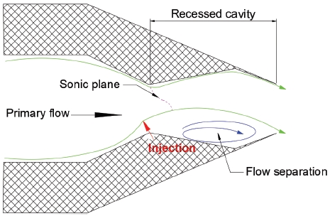
Theoretical, experimental, and numerical methods are widely used to study real applications for incompressible and compressible flows [2-8]. A few fluidic concepts were mentioned to control the deflection of the exhaust flow, such as co-flow TVC[9], counter-flow TVC[10-13], shock vector control (SVC)[14-17], bypass shock vector control (B-SVC)[18], throat-skewing TVC (TS-TVC), and dual-throat nozzle TVC (DTN-TVC). Numerical and experimental studies are conducted by Deere et al. [19,20] for the TS-TVC technique. They argued that it could furnish higher system resultant thrust ratios than the SVC technology. Subsequently, DTN-TVC was developed as an extension to the TS-TVC and investigated due to its higher system resultant thrust ratio without sacrificing other performance[21]. Meanwhile, the minimum efficiency loss is proved[22]. The mechanism of DTN-TVC is shown in Fig. 2. A recessed cavity is formed between two minimum nozzle throats, and one injector is set at the upstream nozzle throat. When the secondary flow is asymmetrically injected at the upstream throat, the flow separation and sonic-plane skewing happen. With respect to the flow separation, some vortices generate at the bottom of the cavity and a low-pressure plateau is found. The DTN-TVC achieves the vectoring control effectiveness by controlling the size of the flow separation and maximizing the pressure difference between the upper and lower dual-throat nozzle surfaces. In order to better perform different operating conditions, Deere et al.[23] and Flamm et al.[24] numerically and experimentally studied the influence of nozzle design variables on an axisymmetric DTN-TVC performance, including the cavity divergence angle, cavity convergence angle, and extent of circumferential injection. Specifically, in terms of the circumferential injection, the case of 60° gives an excellent compromise between the deflection angle and the effective performance. Wu and Kim[25], Shin et al.[26], Wu et al.[27] numerically illustrated that either NPR or injected pressure ratio plays an important role for a DTN-TVC system. Flamm et al.[28] experimentally and computationally studied the effects of geometric variables in a three-dimensional (3D) DTN-TVC system, involving the cavity divergence angle, cavity convergence angle, cavity shape, and secondary injection geometry. They reported that the slot injector can generate higher deflection angles for the injected mass flow rate less than 4% of the primary mass flow rate, compared with the configuration of the hole injector.
To optimize the axisymmetric DTN-TVC performance, several types of research have been discussed in the last few decades; however, relatively few studies are conducted on DTN-TVC in a 3D rectangular supersonic nozzle. Furthermore, the injection angle of the slot injector setup is never been studied systematically. Hence, the aim of the present research is to expound the effects of injection angle on the 3D DTN-TVC performance.
2. Numerical analysis
2.1 Parameter definition
Several effective assessment parameters are defined to quantify the DTN-TVC performance. A deflection angle δβ is defined as the ratio coupled with the momentum flux and pressure force in the normal direction and the ones in the longitudinal direction, which is shown in Eq. (1).
| (1) |
where Fy and Fx represent normal and longitudinal components combined with momentum flux and pressure force, which can be calculated from Eq. (2) and Eq. (3) respectively.
| (2) |
| (3) |
where Ae denotes the area of the supersonic nozzle exit plane. Vex and Vey are longitudinal and normal velocities respectively. m0 and mi are primary and secondary mass flow rates severally. Pe is the area-weighted average static pressure of the nozzle exit plane and Patm is the atmospheric pressure.
In addition, factors that affect the loss and performance of the vectored supersonic nozzles attracted specific interest in earlier DTN-TVC studies[26,27]. To better assess the contribution of the injected flow for a supersonic rectangular nozzle in terms of vectoring performance, another three key coefficients involving injected mass flow ratio mi/m0, system resultant thrust ratio Cs, and efficiency Cr are proposed.
| (4) |
| (5) |
| (6) |
| (7) |
| (8) |
where Fi means the ideally isentropic nozzle thrust force, Fi,p and Fi,s are ideally isentropic thrust force of primary and secondary flows.
2.2 Governing equations
The software of ANSYS Fluent v19.2 is chosen to calculate 3D, compressible, steady Reynolds-averaged Navier-Stokes (RANS) equations. Governing equations are written in Cartesian tensor notation:
Continuity:
| (9) |
Momentum:
| (10) |
Energy:
| (11) |
The term E is the mass-averaged value, which can be expressed as in Eq. (12).
| (12) |
Note that τij represents the stress tensor, which is given by:
| (13) |
where δij represents the viscous heating caused by dissipation.
2.3 Numerical model
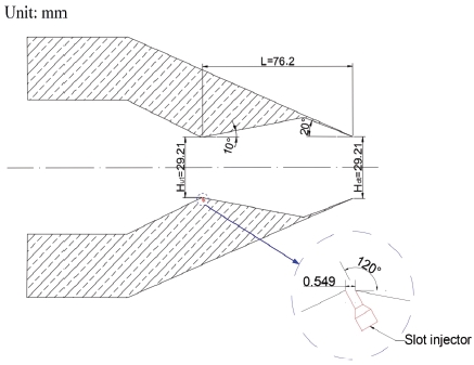
Detailed dimensions of the present dual-throat nozzle model are referred to Flamm et al.[26]. In Fig. 3, the upstream and downstream minimum throat diameters are Hut = Hdt = 29.21 mm, the cavity length is L = 76.2 mm, and the nozzle width is W = 101.6 mm. The divergent and convergent angles of recessed cavity are 10° and 20° respectively. A slot injector is set up at the upstream throat. The slot width is D = 0.549 mm, the slot length is Ls = 101.6 mm, and the injection angle is λ = 120°.
As shown in Fig. 4, a full-domain is created and all boundary conditions are presented. The domain extends 28 times nozzle throat height along the X-axis, 14 times nozzle throat height along the Y-axis, and 7 times nozzle throat height along the Z-axis. To better resolve the separation flow in the recessed cavity, purely structure grids are made and the high grid density is maintained at the upstream nozzle throat, divergent-convergent joint port, and dual-throat nozzle exit. The gradient grid resolution is kept along positive X, Y, and Z axes behind the dual-throat nozzle exit. By considering the viscous effect along the nozzle surfaces, boundary layer meshes are considered on both sides. The boundary layer mesh is composed of 10 cells with a growth factor of 1.2.
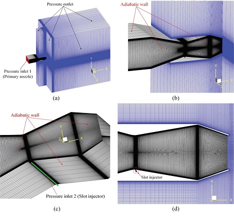
Mesh and boundary conditions: (a) full domain; (b) partial domain; (c) zoom region of the dual-throat nozzle; (d) mesh in the XOY plane.
The computational grid is solved in ANSYS Fluent. An ideal gas is considered as the working fluid and the viscous flow is mathematically analyzed by resolving compressible RANS equations. Second-order accuracy is performed to reveal more flow-field details. The inlet boundaries of the primary and secondary flows are defined as the pressure inlet. The pressure outlet (1 bar) is used to define all exit boundaries. All boundaries of the dual-throat nozzle surfaces are defined as no-slip and adiabatic walls. The stagnation temperature is kept at 297.04 K. The NPR is 4 and the secondary pressure ratio (SPR) is kept at 7.6.
2.4 Mesh convergence study
To clarify the mesh convergence and obtain the least number of elements that can yield accurate results, static pressure profiles along the upper nozzle surface in the symmetry plane are compared in Fig. 5 for three different meshes. The static pressure of the mesh 2 overlaps that of mesh 3, whereas the mesh 1 gives a big difference with mesh 2 and mesh 3. Furthermore, the GCI is discussed to argue the results of mesh convergence studies. Three simulations have a constant refinement ratio, r, in the vicinity of recessed cavity (r = 2). Then the highest pressure ratio in the cavity portion, Puw/P0, along the upper dual-throat nozzle surface is selected as the parameter indicative of grid convergence. Corresponding maximum pressure ratios are 0.74892 (Mesh 1-f1), 0.75892 (Mesh 2-f2), and 0.76453 (Mesh 3-f3). The order of convergence, j, is calculated with the following equation:
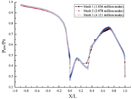
Comparison of static pressure profile along the upper nozzle surface in the symmetry plane for three different meshes.
| (14) |
Then, a Richardson extrapolation is performed with Eq. (15).
| (15) |
The GCI for the fine grid solution is calculated as the factor of safety Fs = 1.25 is fixed[29]. The GCI for mesh 1 and mesh 2 is given in Eq. (16).
| (16) |
The GCI for meshes 2 and 3 can be expressed as in Eq. (17).
| (17) |
Hence,
| (18) |
Thus, mesh 2 is the most suitable choice to conduct present simulations.
3. Results and discussions
3.1 Experimental validation
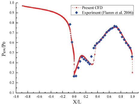
In order to effectively expound flow-field features, the capability of the current numerical methodology and turbulence model is confirmed. The experimental model is a 3D rectangular dual-throat nozzle with an effective injection area of 55.742 mm2, and the injection angle is 150°. The stagnation pressure of the primary flow is 4 bar, the stagnation pressure of the secondary flow is 6 bar. The stagnation temperatures of the primary and secondary flows are 297.04 K. The back pressure is 1 bar, which equals the standard atmospheric pressure. Wang et al.[30] compared numerical results based on the S-A turbulence model, RKE turbulence model, and SST k-ω turbulence model with the experimental data and illustrated that the SST k-ω turbulence model gives the best agreement. Hence, the SST k-ω turbulence model is considered in the present numerical simulations. To analyze experimental and numerical results, normalized static pressure profiles along the upper dual-throat nozzle surface in the symmetry plane are compared in Fig. 6. It is evident that the SST k-ω turbulence model shows an excellent match with experimental data. Therefore, the accuracy of the SST k-ω turbulence model is proved to calculate the DTN-TVC performance.
3.2 Effect of the injection angle
Because of the importance of optimizing the vectoring effect, the DTN-TVC is studied under different injection angles at NPR = 4 and SPR = 7.6. Large-scale injection angles of the slot injector are studied, including λ = 30°, 60°, 90°, 120°, and 150°.
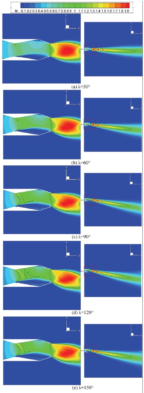
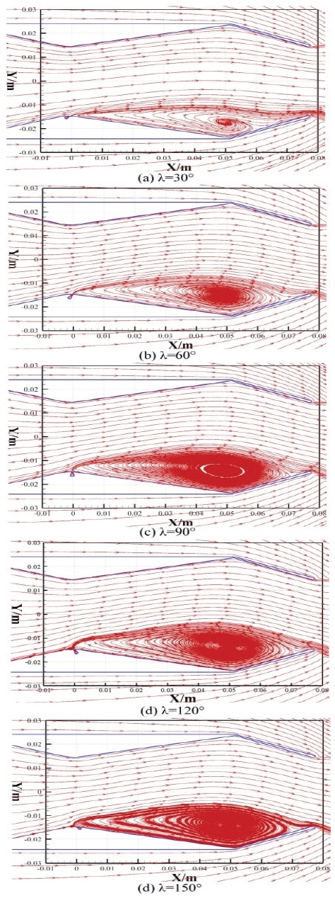
Mach number contours in the symmetry plane for different injection angles are shown in Fig. 7. It can be qualitatively seen that the deflection angle increases with the increasing injection angle till λ = 120°, however, it oppositely decreases in excess of λ = 120°. Furthermore, some changes on the sonic-line skewing are found in zoom regions. In the vicinity of the upstream throat, the extent of the sonic-line increases and the degree of the sonic-line skewing deepens with the increase of the injection angle up to λ = 120°. With a continuous increment of the injection angle, the extent of the sonic-line skewing declines, corresponding to the decay of the deflection angle. Meanwhile, a similar variation of the sonic-line skewing at the downstream throat of the dual-throat nozzle is obtained. The streamlines in the symmetry plane for different injection angles are shown in Fig. 8. In all cases, the separation flow occurs at the bottom of the recessed cavity. As the injection angle is less than 120°, the area of the separation region enlarges with the increase of the injection angle. When λ > 120°, the region of the separation region diminishes.
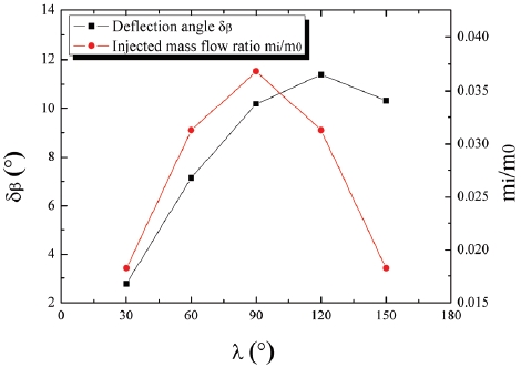
Fig. 9 depicts the evolution of injected mass flow ratio mi/m0 and deflection angle δβ as a function of the injection angle. The injected mass flow ratio rapidly increases up to λ = 90° and then oppositely decreases. In addition, at λ < 120°, the deflection angle rapidly increases with the rise of the injection angle due to the deepening sonic-plane skewing at the upstream and downstream nozzle throats and the enlargement of the separation region. Beyond that, the deflection angle decreases with the increase of the injection angle.
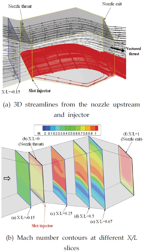
3D streamlines and Mach number contours at different X/L slices of the injection angle at λ = 120° are shown in Fig. 10. The flows in the dual-throat nozzle are composed of two sections, including the mainstream (represented by the black solid lines) from the primary nozzle and the secondary flow (represented by the red solid lines) from the injector. The secondary flow is squeezing and compelling the mainstream to redirect and move downstream toward the opposite direction of the injector. Furthermore, a series of vortexes are rolling up at the bottom of the recessed cavity, as depicted in Fig. 10(a). Therefore, the mainstream oppositely redirects again at the convergent portion of the recessed cavity and finally ejects through the dual-throat nozzle exit at a certain deflection angle owing to the obstruction effectiveness of the convergent cavity. The discrepant flow inside the recessed cavity causes the pressure difference between the upper and lower sides of the recessed cavity, then, the vector thrust is obtained for aerospace vehicles. The Mach number contours at six different X/L slices (X/L = -0.15, 0, 0.25, 0.5, 0.67, and 1) are shown in Fig. 10(b). It can be found that the flow is subsonic at the upstream of the nozzle throat. At the nozzle throat, the secondary flow is choked and the sonic flow is observed at the top and bottom positions inside this plane. Combined with Fig. 7(d), the size and boundary of the separation region can be observed at the bottom of the recessed cavity, as shown in X/L = 0.25, 0.5, and 0.67 slices. With regard to the nozzle exit, it can be seen that the supersonic flow concentrates on the upper side of the plane.
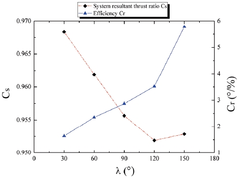
The system resultant thrust ratio Cs and efficiency Cr are shown in Fig. 11 under different injection angles. As the injection angle λ < 120°, the system resultant thrust ratio rapidly decays with the increase of the injection angle. At λ = 120°, the system resultant thrust ratio oppositely increases with the increase of the injection angle. Although the ideally isentropic thrust decreases with the increasing injection angle until λ = 120°, the more rapid decrease of realistic resultant thrust leads to a decreasing system resultant thrust ratio. When the injection angle exceeds 120°, both ideally isentropic thrust and realistic resultant thrust oppositely increase; however, a faster rise of realistic resultant thrust causes the increase of the system resultant thrust ratio. Additionally, the relationship between the efficiency and the injection angle is demonstrated to describe energetic DTN-TVC performance. The efficiency increases with the increasing injection angle. Specifically, the efficiency linearly increases, as the injection angle is less than 120°. However, the efficiency increases abruptly, when the injection angle is more than 120°. By analyzing Eq. (8), although the deflection angle slightly decreases for λ = 150°, compared with that at λ = 120°, a more rapid decrease of the injected mass flow ratio results in an increase of the efficiency.
4. Conclusions
The subject of the present work is to study the possible engineering applications of the DTN-TVC system in a 3D supersonic rectangular nozzle. Numerical simulations are conducted to analyze the effects of injection angle on the vector performance. An excellent agreement between the numerical result and the experimental data proves that the SST k-ω turbulence model can accurately predict the main features.
The injection angle significantly affects DTN-TVC performance. The main characteristics are illustrated, such as the complex flow separation in the recessed cavity and sonic-plane skewing at the upstream and downstream nozzle throats. The highest deflection angle is obtained at λ = 120° due to the maximal sonic-plane skewing at the upstream and downstream nozzle throats and the largest vortex region at the bottom of the recessed cavity. The system resultant thrust ratio decreases with the increase of the injection angle. Up to λ = 120°, the system resultant thrust ratio oppositely increases with the rise of the injection angle. The lowest system resultant thrust ratio is gained at λ = 120°. If the system resultant thrust ratio is extrapolated to quantify the performance of any other propulsion nozzle, the system resultant thrust ratio also decreases initially and then oppositely increases for the increasing injection angle. This is related to the initially increasing shock loss and subsequently decreasing shock loss in the recessed cavity. In addition, the efficiency continuously increases with the increase of the injection angle.
Nomenclature
| Ae : | Exit area |
| Cr : | Efficiency |
| Cs : | System resultant thrust ratio |
| D : | Slot width |
| f : | Maximum pressure ratio |
| Fi : | Ideally isentropic thrust force |
| Fi,p : | Ideally isentropic thrust force of the primary flow |
| Fi,s : | Ideally isentropic thrust force of the secondary flow |
| Fx : | Longitudinal thrust force |
| Fy : | Normal thrust force |
| Fz : | Lateral thrust force |
| Hut : | Height of the upstream throat |
| Hdt : | Height of the downstream throat |
| j : | Order of convergence |
| L : | Cavity length |
| Ls : | Slot length |
| m0 : | Primary mass flow rate |
| mi : | Secondary mass flow rate |
| NPR : | Nozzle pressure ratio |
| P0 : | Stagnation pressure of the primary flow |
| Patm : | Ambient pressure |
| Pe : | Area-weighted average static pressure of the dual-throat nozzle exit plane |
| Pi : | Stagnation pressure of the secondary flow |
| Puw : | Static pressure along the upper nozzle surface in the symmetry plane |
| r : | Refinement ratio |
| Rg : | Gas constant |
| SPR : | Secondary pressure ratio |
| T0 : | Stagnation temperature of the primary flow |
| Ti : | Stagnation temperature of the secondary flow |
| Vex : | Axial velocity |
| Vey : | Normal velocity |
| w : | Width of the dual-throat nozzle |
| γ : | Specific heat ratio |
| δβ : | Deflection angle |
| θ : | Convergent or divergent angle of the recessed cavity |
Acknowledgments
[이 논문은 한국추진공학회 2019년도 추계학술대회(2019. 11. 27-29, 해운대 그랜드호텔) 발표논문을 심사하여 수정·보완한 것임.]
This work was supported by the National Research Foundation of Korea (NRF) grant funded by the Korea government(MSIP) (No. NRF-2016R1A2B3016436).
References
- Sutton, G.P. and Biblarz, O., “Rocket Propulsion Elements,” Wiley, Chichester, U.K., 2001.
-
Lin, Z., Sun, X.W., Yu, T.C., Zhang Y.F., Li, Y. and Zhu, Z.C., “Gas-Solid Two-Phase Flow and Erosion Calculation of Gate Valve Based on the CFD-DEM model,” Powder Technology, Vol. 366, pp. 395-407, 2020.
[https://doi.org/10.1016/j.powtec.2020.02.050]

-
Zheng, X., Lin, Z. and Xu, B.Y., “Thermal Conductivity and Sorption Performance of Nano-Silver Power/FAPO-34 Composite Fin,” Applied Thermal Engineering, Vol. 160, pp. 114055, 2019.
[https://doi.org/10.1016/j.applthermaleng.2019.114055]

-
Lin, Z., Liu, Z.X., Liu, Q. and Li, Y. “Fluidization Characteristics of Particles in a Groove Induced by Horizontal Air Flow” Powder Technology, Vol. 363, pp. 442-447, 2020.
[https://doi.org/10.1016/j.powtec.2020.01.022]

-
Tao, J.Y., Lin, Z., Ma, C.J., Ye, J.H, Zhu, Z.C., Li, Y. and Mao, W. “An Experimental and Numerical Study of Regulating Performance and Flow Loss in a V-Port Ball Valve,” Journal of Fluid Engineering, Vol. 142, No. 2, pp. 021207, 2020.
[https://doi.org/10.1115/1.4044986]

-
Zhang, G., Zhang, Y.F., Liu, Q., Li, Y. and Lin, Z., “Experimental Study on the Two-Phase Flow of Gas-Particles through a Model Brake Valve,” Powder Technology, Vol. 367, pp. 172-182, 2020.
[https://doi.org/10.1016/j.powtec.2020.03.047]

-
Wu, K.X., Zhang, G. and Kim, H.D., “Study on the Mach and Regular Reflections of Shock Wave,” Journal of Visualization, Vol. 22, No. 2, pp. 1-21, 2019.
[https://doi.org/10.1007/s12650-018-00542-5]

-
Lin, Z., Yin, D.P., Tao, J.Y., Li, Y., Sun, J. and Zhu, Z.C., “Effect of Shaft Diameter on the Hydrodynamic Torque of Butterfly Valve Disk,“ Journal of Fluid Engineering, Vol. 142, No. 11, pp. 111202, 2020.
[https://doi.org/10.1115/1.4047795]

-
Heo, J.Y. and Sung, H.G., “Fluidic Thrust-Vector Control of Supersonic Jet Using Coflow Injection,” Journal of Propulsion and Power, Vol. 28, No. 4, pp. 858-861, 2012.
[https://doi.org/10.2514/1.B34266]

-
Wu, K.X., Jin, Y.Z. and Kim, H.D., “Fluidic Thrust Vector Control Based on Counter-Flow Concept,” Proceedings of the Institution of Mechanical Engineers, Part G: Journal of Aerospace Engineering, Vol. 233, No. 4, pp. 1412-1422, 2018.
[https://doi.org/10.1177/0954410017752580]

-
Wu, K.X., Zhang, G., Kim, T.H. and Kim, H.D., “Numerical Parametric Study on Three-Dimensional Rectangular Counter-Flow Thrust Vectoring Control,” Proceedings of the Institution of Mechanical Engineers, Part G: Journal of Aerospace Engineering, 2020.
[https://doi.org/10.1177/0954410020925602]

-
Wu, K.X., Jin, Y.Z. and Kim, H. D., “Hysteresis Behaviors in Counter-Flow Thrust Vector Control,” Journal of Aerospace Engineering, Vol. 32, No. 4, pp. 04019041, 2019.
[https://doi.org/10.1061/(ASCE)AS.1943-5525.0001027]

-
Wu, K.X., Kim, T.H., James, J.K. and Kim, H.D., “Assessment of the Counter-Flow Thrust Vector Control in a Three-Dimensional Rectangular Nozzle,” Journal of the Korean Society of Propulsion Engineers, Vol. 24, No. 1, pp. 34-46, 2020.
[https://doi.org/10.6108/KSPE.2020.24.1.034]

-
Zmijanovic, V., Lago, V. and Chpoun, A., “Thrust Shock Vector Control of an Axisymmetric Conical Supersonic Nozzle via Secondary Transverse Gas Injection,” Shock Waves, Vol. 24, No. 1, pp. 97-111, 2014.
[https://doi.org/10.1007/s00193-013-0479-y]

-
Wu, K.X., Kim, T.H. and Kim, H.D., “Theoretical and Numerical Analyses of Aerodynamic Characteristics on Shock Vector Control,” Journal of Aerospace Engineering, Vol. 33, No. 5, pp. 1-26, 2020.
[https://doi.org/10.1061/(ASCE)AS.1943-5525.0001169]

-
Wu, K.X. and Kim, H.D., “Numerical Study on the Shock Vector Control in a Rectangular Supersonic Nozzle,” Proceedings of the Institution of Mechanical Engineers, Part G: Journal of Aerospace Engineering, Vol. 233, No. 13, pp. 4943-4965, 2019.
[https://doi.org/10.1177/0954410019834133]

-
Wu, K.X. and Kim, H.D., “Fluidic Thrust Vector Control Using Shock Wave Concept,” Journal of the Korean Society of Propulsion Engineers, Vol. 23, No. 4, pp. 10-20, 2019.
[https://doi.org/10.6108/KSPE.2019.23.4.010]

-
Deng, R. Y. and Kim H. D. “A Study on the Thrust Vector Control Using a Bypass Flow Passage,” Proceedings of the Institution of Mechanical Engineers, Part G: Journal of Aerospace Engineering, Vol. 229, No. 9, pp. 1722-1729, 2015.
[https://doi.org/10.1177/0954410014558693]

-
Deere, K. A., Berrier, B. L., Flamm, J. D. and Johnson, S. K., “Computational Study of Fluidic Thrust Vectoring Using Separation Control in a Nozzle,” 21st AIAA Applied Aerodynamics Conference, O.R., USA, AIAA 2003-3803, 2003.
[https://doi.org/10.2514/6.2003-3803]

-
Deere, K.A., Berrier, B.L., Flamm, J.D. and Johnson, S.K., “A Computational Study of a New Dual Throat Fluidic Thrust Vectoring Nozzle Concept,” 41st AIAA/ASME/SAE/ASEE Joint Propulsion Conference & Exhibit, T.U., USA, AIAA 2005-3502, 2005.
[https://doi.org/10.2514/6.2005-3502]

-
Flamm, J.D., Deere, K.A., Berrier, B.L. and Johnson, S.K., “An Experimental Study of a Dual Throat Fluidic Thrust Vectoring Nozzle Concept,” 41st AIAA/ASME/SAE/ASEE Joint Propulsion Conference & Exhibit, T.U., USA, AIAA 2005-3503, 2005.
[https://doi.org/10.2514/6.2005-3503]

- Ferlauto, M. and Marsilio, R. “Numerical Simulation of Fluidic Thrust-Vectoring,” Journal of Aerospace Science, Technology and Systems, Vol. 88, pp. 1-8, 2009.
-
Deere, K.A., Flamm, J.D., Berrier, B.L. and Johnson, S.K., “Computational Study of an Axisymmetric Dual Throat Fluidic Thrust Vectoring Nozzle Concept for Supersonic Aircraft Application,” 43rd AIAA/ASME/SAE/ASEE Joint Propulsion Conference & Exhibit, C.I., USA, AIAA Paper 2007-5085, 2007.
[https://doi.org/10.2514/6.2007-5085]

-
Flamm, J.D., Deere, K.A., Mason, M.L., Berrier, B.L. and Johnson, S.K., “Experimental Study of an Axisymmetric Dual Throat Fluidic Thrust Vectoring Nozzle for a Supersonic Aircraft Application,” 43rd AIAA/ASME/SAE/ASEE Joint Propulsion Conference & Exhibit, C.I., USA, AIAA Paper 2007-5084, 2007.
[https://doi.org/10.2514/6.2007-5084]

-
Wu, K.X. and Kim, H.D., “Study on Fluidic Thrust Vector Control Based on Dual-Throat Concept,” Journal of the Korean Society of Propulsion Engineers, Vol. 23, No. 1, pp. 24-32, 2019.
[https://doi.org/10.6108/KSPE.2019.23.1.024]

-
Shin, C.S., Kim, H.D., Setoguchi, T. and Matsuo, S., “A Computational Study of Thrust Vectoring Control Using Dual Throat Nozzle,” Journal of Thermal Science, Vol. 19, No. 3, pp. 486–490, 2010.
[https://doi.org/10.1007/s11630-010-0413-x]

- Wu, K.X., Kim, T.H. and Kim, H.D., “Numerical Study of Fluidic Thrust Vector Control Using Dual Throat,” Journal of Applied Fluid Mechanics, Vo. 14, No. 1, 2021.
-
Flamm, J.D., Deere, K.A., Berrier, B.L. and Johnson, S.K., “Design Enhancements of the Two-Dimensional, Dual Throat Fluidic Thrust Vectoring Nozzle Concept,” 3rd AIAA Flow Control Conference, S.F., USA, AIAA 2006-3701, 2006.
[https://doi.org/10.2514/6.2006-3701]

-
Wu, K.X., Raman, S.K., Vignesh, R.P.S., Zhang, G. and Kim, H.D. “Effect of the Wall Temperature on Mach Stem Transformation in Pseudo-Steady Shock Wave Reflections,” International Journal of Heat and Mass Transfer, Vol. 147, pp. 118927, 2020.
[https://doi.org/10.1016/j.ijheatmasstransfer.2019.118927]

-
Wang, Y.S., Xu, J.L., Huang, S., Lin, Y.C. and Jiang, J.J., “Experimental and Numerical Investigation of an Axisymmetric Divergent Dual Throat Nozzle,” Proceedings of the Institution of Mechanical Engineers, Part G: Journal of Aerospace Engineering, Vol. 234, No. 3, pp. 563-572, 2019.
[https://doi.org/10.1177/0954410019872089]

