RDE 기반 PGC 추진기관 연구 동향, Part II: 응용연구
Copyright Ⓒ The Korean Society of Propulsion Engineers
This is an Open-Access article distributed under the terms of the Creative Commons Attribution Non-Commercial License (http://creativecommons.org/licenses/by-nc/3.0) which permits unrestricted non-commercial use, distribution, and reproduction in any medium, provided the original work is properly cited.
초록
앞서의 논문을 통하여 RDE와 관련된 초기의 기초 연구를 살펴보았다. 최근에는 이를 바탕으로 동력장치 및 항공우주 추진기관에 적용하기 위한 연구가 활발히 진행되고 있다. 각국에서는 대학과 기업 그리고 연구소의 공동 연구를 통하여 가스터빈 및 액체 로켓 엔진이나 복합사이클 엔진으로의 응용연구가 활발히 진행되고 있어, 본 논문에서는 앞서의 Part I 논문에 이어 세계 곳곳에서 진행되고 있는 실질적인 RDE 응용연구에 대한 포괄적인 고찰을 수행하였다.
Abstract
The early basic studies on RDE has been surveyed in the previous paper. Recently active researches are carrying on for the application to the power plant and aerospace propulsion systems. Collaboration researches are going on for the application of RDE for the gas turbine, liquid rocket and combined cycle engines in many countries. Following the previous Part 1 paper, present paper is intended to provide the comprehensive survey of recent worldwide efforts on the realistic application of RDE.
Keywords:
Rotating Detonation Engine(RDE), Constant Volume Combustion(CVC), Pressure Gain Combustion(PGC)키워드:
회전 데토네이션 엔진, 정적연소, 압력증가연소1. 서 론
데토네이션 파를 이용하여 유체역학적으로 CVC를 구현한 PGC 추진기관의 사이클 효율은 15~30% 가량 증가시킬 수 있는 “Game-Changing” 기술로 여겨져 지난 십여 년간 해외에서 활발한 연구가 진행되고 있으나 국내에서는 관련 기초연구 일부와 PDE 방식의 실험 연구가 일부 진행 중이다[1]. PDE 방식의 PGC 연구에 대해서는 이전의 동향 고찰에서 살펴본 바 있으며[1], 앞서의 Part I의 논문을 통하여 과거에 진행된 RDE 기초 연구에 대하여 살펴보았다. 본 논문에서는 과거 RDE에 대한 세계 각지에서 진행된 연구를 통하여 최근 진행되고 있는 응용연구의 동향을 살펴보았다. 이를 위하여 2장에서는 최근 진행된 이론 및 해석 연구에 대하여 살펴보았으며, 3장에서는 로켓엔진 형태로 개발되고 있는 최근의 RDE 연구 성과와 함께, 데토네이션의 높은 열효율을 기존의 가스터빈 엔진과 결합하여 전체적인 효율상승을 목표로 연구 중인 복합엔진 연구 사례를 소개하였다.
2. RDE 이론 및 해석 연구
RDE 내부 유동장은 수 km/s 의 데토네이션 속도와 고온 유동. 곡면의 형상 등으로 가시화 및 정밀 계측이 매우 어려운 특징을 가진다. 따라서 CFD 해석은 RDE 연구의 초기부터 실험적 가시화로 파악하기 어려운 내부 유동의 특징을 파악하고, 성능에 영향을 줄 수 있는 여러 변수의 영향을 파악하는 주요 도구로 이용되었다.
2.1 CFD 기반 RDE 성능 연구
Yi 등은 Adaptive Mesh Refinement (AMR) 기법을 이용하여 데토네이션 셀 구조를 포착하는 정밀한 전산유체해석을 바탕으로 여러 조건 및 형상에서 RDE의 성능을 분석하였다. 동일한 조건에서 PDE와 비교한 성능 분석에서 RDE가 더 우수한 성능을 가질 수 있으며, 성능은 분사 조건에 크게 의존하고 데토네이션 파의 수나, 연소기 길이 등에는 크게 영향을 받지 않음을 보였다[2]. University of Texas at Arlington(이하 Texas Arlington 대학)의 Lu와 Braun 등은 RDE를 Brayton 사이클의 싱글 스트림으로 가정하여 마하수 1 ~ 5 범위에서 공기 흡입 PDE와 RDE가 정상상태인 조건의 열역학 사이클을 계산하였다[3-5]. 수소 연료의 경우 약 4000 s, 메탄 연료의 경우 약 2000 s의 비추력과 마하 2.5 ~ 5.0의 비행조건 중에서 마하 3.5가 가장 높은 비추력을 가지는 결과를 얻었다. 이후 Humphrey 사이클과 비교해 기존의 CVC 사이클과 데토네이션의 ZND 사이클의 차이점을 분석하였다.
Naval Research Laboratory (NRL)의 Schwer 와 Kailasanath는 고정밀도의 이차원, 삼차원 CFD 해석을 통하여 데토네이션과 아음속 연소, 충격파, 팽창파, 혼합 경계층이 혼재하는 RDE 내부의 복합적인 연소 유동을 연구하였다[6,7]. H2-Air의 공급 기체 정체조건이 10 atm, 300 K, 외부 압력 1 atm 조건을 기준으로 압력비를 5 ~ 30까지 변화시키며 계산한 결과 비추력이 3845 s에서 5560 s까지 변하였다. 또한 발생된 데토네이션에서 고압 및 팽창 영역과 외부 저압 영역의 상호 작용에 의한 2차 충격파가 성능 손실에 많은 부분을 차지함을 알 수 있었다.
NRL의 Kailasanath와 Connecticut 대학의 Nordeen 등은 RDE의 열역학 사이클 분석을 수행하였다[8,9]. 에너지 성능 분석과 추세 식별을 통하여 기존의 가스터빈 및 램제트 엔진과 RDE의 열역학 사이클의 비교를 통하여 공급 인젝터와 벽면의 면적비가 미치는 영향, 연소실 평균 직경과 길이의 영향 등 형상 변수에 따른 성능 영향을 CFD을 통하여 분석하였다. 해석 결과 분사기 면적비 증가는 데토네이션 높이와 전면부 압력, 비추력을 상승시켰으나, 연소실 반경과 길이의 변화에는 그 영향이 미미하였다. 하지만 공급 압력이 특정 압력보다 낮으면 연소실 길이는 전면부 압력과 비추력에 영향을 주었다[10].
2.2 CFD 기반 추진제 공급 조건 연구
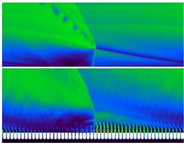
이전의 연구로부터 분사 조건이 RDE 성능에 영향을 미치는 주요 변수임을 알 수 있었으므로 NRL의 Schwer 등은 분사기의 영향을 살펴보기 위한 CFD 연구를 수행하였다[11]. 길이 10 mm, 직경 1.131 mm의 분사기가 5.655 mm 간격으로 30 mm 길이에 걸쳐 50개가 뚫려 있는 조건의 분사기를 경계 조건, 생성항 및 해석영역에 포함하여 모델링한 경우 각각 5,331, 4,955, 4,918 s의 비추력 결과를 얻었으며, 이를 통해 불연속적인 분사기의 영향과 압력 상승에 따른 역류 가능성을 이론적으로 확인할 수 있었다.
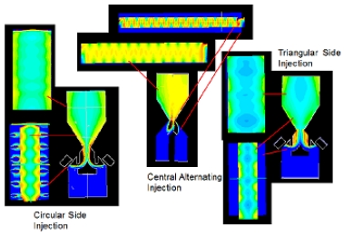
Stoddard와 Gutmark은 분사기 주변의 화염유지를 줄여 후기 데토네이션의 hot dead zone을 줄이는 것을 목표로 하여 구체적인 설계연구를 수행하였다[12]. 삼차원 CFD 해석을 활용하여 Fig. 4와 같이 다양한 형상에 따른 유동 특성을 분석하여 기존의 슬릿 분사기 주변의 화염유지 문제를 해결할 수 있는 새로운 분사기 형상을 제안하였다.
추진기관의 공급 조건에 따라 결정되므로 Schwer와 Kailasanath는 공급 압력과 주위 대기의 압력비의 영향에 대한 연구를 수행하였다[13]. 압력비 2~20조건에서 RDE의 비추력을 계산하여 2,630 ~ 5,500 s의 결과를 얻었으며. RDE 연소실 단면적이 변하는 조건에서 각 면적비의 변화율에 따라 성능변화를 계산해 반경이 줄어들수록 비추력이 상승하는 결과를 얻었다[14].
2.3 효율적 해석 기법 연구
내부 유동의 상세한 특징을 파악하기 위한 정밀한 CFD 해석은 실험적으로 가시화가 어려운 내부 유동의 물리적 특징에 대하여 구체적으로 이해할 수 있게 하여주고, 공학적 해결방향을 제시하거나, 설계 결과는 확인 하는 용도로 이용될 수 있지만, 실용적인 설계도구로 이용되기 위해서는 매우 빨리 해석 결과를 제시할 수 있는 방법이 필요하다.
NASA의 Paxson 등은 수치해석의 계산 효율을 높이기 위하여 상대 좌표계를 이용하여 상대적으로 단순한 이차원 CFD 프로그램을 작성하였다[11]. 이를 통하여 다양한 설계 변수의 정상상태의 결과와 분석을 보다 빠르게 도출하였으며, 계산된 결과 역시 기존 결과와 비교해 차이가 크지 않아 RDE 설계에서 전체적 성능 변화를 빠르게 비교할 수 있다[15].
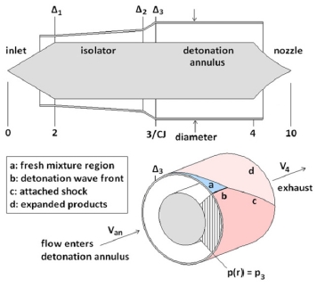
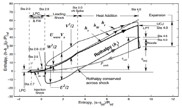
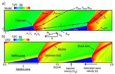
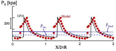
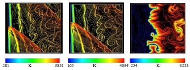
그러나, 반복연산과 수렴과정을 필요로 하는 CFD 해석은 시간 비용이 크므로, 간략화된 이론적 해석을 기반으로 한 대략적 성능 예측 방법은 여전히 유용한 설계도구이다. Maryland 대학의 Fievisohn과 Yu는 Chapmann-Jouguet (C-J) 데토네이션 이론 해석과 특성곡선해법(Method of Characteristics, MOC)을 결합하여 RDE 내부 유동의 기본적인 구조를 이론적으로 예측할 수 있는 방법을 제안하였다[16]. 같은 시기 Purdue 대학의 SoU.S.A. 등도 개념적으로 동일한 MOC 해석도구 개발연구를 별개로 수행하였으며 가스터빈 엔진을 결합한 복합엔진의 해석을 수행하였다[17]. Fig. 5, 6은 Sousa 등의 연구에서 C-J/MOC 이론 해석과 CFD의 해석결과를 비교한 그림이다. 이론 해석은 경험식을 일부 이용하여야 하며, 점성효과 등의 영향은 고려하기 어려운 단점이 있지만, 빠르게 근사해를 구할 수 있는 장점이 있다.
2.4 데토네이션 구조 및 안정성 연구
RDE 연구 초기에는 낮은 속도로 공급되는 혼합기체의 수직 방향으로 전파되는 데토네이션 파의 존재 및 안정성에 대하여 의구심이 있었다. Fujiwara 등은 C-J 데토네이션 및 경사 데토네이션(Oblique Detonation Wave)와의 비교를 통하여 RDE 내에서 데토네이션 파가 안정화 될 수 있음을 설명하였다[18].
많은 실험 및 CFD연구에서 작동 조건에 따라 RDE 내에 다수의 데토네이션 파가 형성되는 것이 관찰되었다. Wolanski 등은 많은 실험과 해석 연구를 통하여 RDE 연소기 내에 형성되는 데토네이션 파의 수(Detonation Wave Number), W라는 무차원 수를 제시하였다[19]. W는 Eq. 1과 같이 데토네이션 파 전파 시간을 미연 가스의 공급시간으로 나눈 값으로 데토네이션이 유지되기 위한 임계 공급 부피와 생성되는 데토네이션의 숫자와의 상관관계이다. W를 구하기 위한 각 변수들은 손쉽게 구할 수 있는 값들로 데토네이션의 안정성을 쉽게 예측할 수 있게 해준다.
| (1) |
여기서, tr=πd/uD 은 데토네이션 파가 직경 d의 연소실을 1 회전하는데 걸리는 시간이며, uD는 데토네이션 속도이고, 로 정의되는 미연가스 공급 시간이다. 여기서 임계 부피는 다음과 같이 정의되며,
| (2) |
di, do 는 연소실 내·외경, lcr는 미연 혼합 가스의 특성 길이, 는 미연 혼합기체의 체적 유량이다.
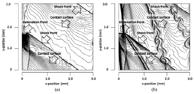
관 내부를 전파하는 일반적인 데토네이션 파와 달리, RDE 내의 데토네이션은 한쪽 끝이 열려있는 상태이기 때문에 개방측단(lateral relief)의 데토네이션 삼중점 구조와 안정성이 학술적 관심이 되었다. Aoyama Gakuin 대학의 Hayashi 등은 연소기 크기, 공급조건, 점화에너지 및 격자해상도 등에 대한 다수의 CFD 해석을 수행하였으며, 이를 통하여 데토네이션 파와 경사 충격파, 미연과 기연 가스의 간섭에 의한 셀 구조와 삼중점 및 데토네이션 안정성에 대하여 보다 상세한 이해가 증진되었다[20-22].
개방측단을 가진 데토네이션의 특징에 대해서는 대기중 폭발에 의한 데토네이션 발생과 관련하여 오래전 Sichel과 Foster[23] 및 Vasil'ev와 Zak[24] 등에 의하여 실험 결과를 바탕으로 이론적으로 연구된 바가 있으나, RDE와 관련하여 AFRL에서 Cho 등이 개방측단의 살피기 위하여 PDE에 개방측단을 가지는 연소기를 부착한 이이차원 RDE모사 연소기를 제작하여 새로이 가시화 실험 연구를 시작하였다[25].
이차원 RDE모사 연소기는 데토네이션과 분사기의 상호작용을 연구하기 위한 연구로도 이용되고 있다. Maryland 대학의 Burr와 Yu는 PDE에서 발생된 데토네이션이 분사, 혼합 유동과 만나서 재점화하는 과정을 가시화 하는 실험연구를 진행 중이며[26], 이에 대하여 난류 혼합 및 데토네이션 발생특성을 밝히기 위하여 Masselot 등이 고정밀 CFD해석 연구를 시작하였다[27].
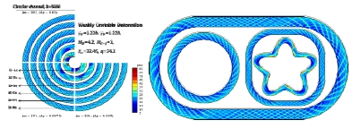
한편, RDE에서 데토네이션 파는 원주 방향으로 진행하기 때문에 대부분의 연구는 진행방향 특성에 대해서 이루어져 왔고, RDE를 형성하는 환형 연소기의 폭과 반경방향 효과에 대해서는 연구가 부족한 편이었다. 부산대의 Choi 등은 비용이 많이 필요한 삼차원 해석대신 간단한 방법으로 RDE의 반경방향 곡률효과를 연구하기 위하여 반경이 서로 다른 원형 관내를 전파하는 이차원 데토네이션 해석을 통하여 임계반경보다 큰 곡률을 가지는 관에서만 안정된 셀 구조를 가질 수 있음을 보였으며, 데토네이션 파의 전파속도는 중앙부에서는 C-J 속도를 가지지만, 안쪽은 “under-driven”, 바깥쪽은 “over-driven” 특징을 가짐을 보였다[28]. 아울러 국소 곡률반경이 임계반경 보다 크면, RDE의 단면이 원형일 필요는 없으며 임의의 형상을 가질 수 있음을 CFD해석을 통하여 보여주었다[29].
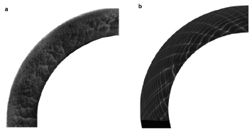
Choi 등의 연구는 곡률 효과에 대한 연구를 유발하였다. 여 Kasahara 등은 여러 곡률을 가지는 이차원 연소기를 제작하여 가시화 실험을 수행하여 임계 반경보다 작은 경우의 바깥쪽에서 굽어진 “over-driven” 경사 데토네이션의 특징을 가짐을 보였고, 굽어진 데토네이션에 대한 이론적 해석을 수행하였다[30]. 아울러 Sugiyama 등은 CFD해석을 통하여 “over-driven” 조건에서는 데토네이션 파의 전파가 불안정하여질 수 있음을 보였으며[31], Jian 등은 굽은 관내의 데토네이션 전파 특성에 대한 보다 상세한 분석을 수행하였고[32], Short 등은 곡률 효과에 대한 Detonation Shock Dynamics (DSD) 모델을 제시하였다[33]. Eude 등[34], Jiang 등[35] 및 Pan 등[36]이 삼차원 CFD해석을 수행하여 RDE 내의 데토네이션 파의 삼차원 구조에 대한 특징을 살펴보았으며, 이중 Pan 등은 실험과 해석의 비교 연구를 통하여 안쪽과 바깥쪽 벽면에서 데토네이션 셀 구조의 차이를 확인하였다.
북경대의 Tang 등은 삼차원 CFD 해석을 통하여 중앙부가 없는 로켓 연소실과 같은 원통형의 RDE 연소기에서도 데토네이션이 안정적으로 형성되어 전파 될 수 있음을 보였다[37].
이에 앞서 Choi 등은 1960년대 액체로켓엔진 개발 초기 단계에 연구된 연소불안정 압력계측 결과의 바탕으로 액체로켓의 접선방향 연소불안정이 RDE 데토네이션 현상임을 논의한바 있으며[38], 이를 적극적으로 이용한 RDE 연소방식의 액체 로켓 연소기를 제안한 바 있다[39].
3. RDE 액체로켓 및 가스터빈 연구
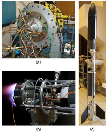
RDE의 PGC 효과를 이용하면 고려하면 액체로켓의 비추력을 크게 향상시킬 수 있기에 액체 로켓은 Nicholls 등의 연구[40] 및 Falempin 등의 연구[41] 등, RDE 연구의 초기 단계에서부터 주요 적용 대상으로 고려되었으며 Wolanski 등은 일련의 연구 결과를 바탕으로 2016년 RDE 로켓을 설계하였으며, 조립된 상태로 서브시스템 실험과 연구 등 세부 조정 중이다. 향후 RDE 로켓의 초기 실험은 안정성을 고려해 기체 메탄과 산소를 이용하여 시험 발사할 예정이며 발사와 회수 등의 시스템 연구를 소형과학로켓 프로그램을 통하여 진행 중이다[42-45].
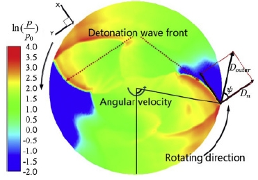
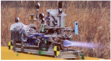
Nagoya 대학은 JAXA 후원의 상단 킥모터 RDE 개발 연구를 진행 중이다[46,47]. 연소실의 빠른 열확산을 위하여 구리재질로 연소실을 제작하였으며, 공급 속도를 증가위하여 수축-확산 노즐 형태로 분사기를 제작하였다. Fig. 13과 같이 독립모듈로 제작된 추진시스템을 레일을 이용하여 성공적인 지상실험을 수행하였다[48].
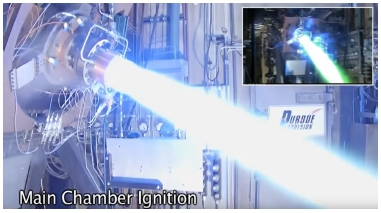
미국에서는 앞서 언급한 바와 같이 가장 큰 로켓 엔진 회사라고 할 수 있는 Aerojet-Rocketdyne 등에서 RDE 엔진 개발을 위한 연구를 활발히 수행중이며[40], 러시아에서는 2014년 로켓엔진 기업인 NPO Energomash 산하에 “데토네이션 액체로켓엔진“ 연구소를 설립하여 최근 케로신-산소 추진제의 RDE 엔진 실험을 성공적으로 수행하였다[49].
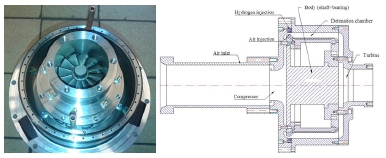
앞서 2장과 5장에서 언급하였던 바와 같이 RDE를 이용한 PGC 연구가 관심을 얻는 데에는 가스터빈 엔진효율 증가를 위한 DARPA의 VULCAN 사업에 영향을 크게 받았다. 가스터빈과 RDE를 직접 연계한 연구개발 프로그램이 눈에 띄는 곳은 폴란드와 미국이다. 폴란드의 경우 Wolanski와 Kindracki등은 GTD-350 가스터빈 엔진의 연소기를 RDE로 대체한 복합엔진을 제작하여 연구하고 있다[50]. Jet-A 연료와 수소연료를 보조적으로 이용한 실험에서 안정적인 데토네이션 생성과 유지가 가능하였으며, 이론적으로 기존 Brayton 사이클에 비해 61.4% 효율상승을 기대하고 있다[50,51].
미국에서는 국방부(Department of Defense, DoD)와 에너지부(Department of Energy) 모두 PGC 개발을 지원하고 있다. Office of Naval Research (ONR) 지원하에 해군대학원(Naval Postgraduate School, NPS)은 RDE의 성능 도출에 미치는 엔진 흡입특성을 연구하였으며, 해군연구소(Naval Research Laboratory, NRL)에서 CFD 해석을 담당하였다. NPS는 HyPerComp상와 Connecticut 대학, Aerojet Rocketdyne 연구팀의 RDE 가스터빈 엔진을 지원하고 있으며 RDE의 비정상 유동에 의하여 구동되는 터빈 효율을 측정하였다. Michigan 대, Pennsylvania 주립대 및 Purdue 대학은 국가에너지기술연구소(National Energy Technology Laboratory, NETL)의 후원하에 University Turbine Systems Research (UTSR) 프로그램으로 RDE 개발을 시작하였다. NETL은 천연 가스 RDE 기술을 발전시키기 위해 Aerojet Rocketdyne에 3년간의 2 단계 프로그램을 수여하였다. NETL은 PGC를 가스터빈의 주요 연구 분야로 선정하여 기본적인 벤치 스케일 실험, 실험실 규모 실험 및 해석 연구를 포함하는 자체 내부 연구를 수행하였다. AFRL은 NETL과 협력하여 T63 가스터빈 엔진에 연결된 RDE 연소기 실험을 통하여 터빈 경계조건과 터빈성능 및 질소 산화물 배출을 평가하였으며, 해석 결과를 바탕으로 배출물을 허용 가능한 수준으로 유지할 수 있음을 확인하였으며, 65% 이상의 열효율 획득을 목표로 하고 있다. NASA Glenn 연구센터는 AFRL과 협력하여 RDE 모델링, 검증 및 최적화 연구를 수행하였다[53,54-56].
4. 결 론
데토네이션 현상을 이용하여 열효율 및 추진 성능을 획기적으로 향상시킬 수 있을 것으로 기대되는 PGC 개념의 추진기관 연소기인 RDE에 대한 연구가 세계적으로 활발히 진행되고 있다. 지난 part I과 본 part II 논문을 통하여 국내의 RDE 연구를 수행하기에 앞서 과거와 최근 진행 중인 연구들에 대하여 살펴보았다. 최근 폴란드의 경우 RDE 로켓 엔진을 이용한 과학로켓을 발사할 단계에 있으며, 미국 역시 RDE 로켓뿐만 아니라 기존의 가스터빈과의 결합으로 현재 정체되어 있는 가스터빈 기술의 한계를 극복하려 한다. 가까운 일본에서는 제작된 RDE를 실용화를 위한 실험 단계에 있고, 러시아와 그 밖의 유럽 역시 이 기술을 주목하고 있다. 이런 열기는 중국, 싱가포르, 대만 등 아시아 국가도 마찬 가지로 기술 확보를 위하여 활발히 연구하고 있다. 향후 연구 진행을 위한 참고 자료로써, 각 연구에서의 핵심 내용을 살펴보았으며, 이를 바탕으로 향후 국내의 RDE 실험을 위한 기초적인 정보를 제시하였다. 향후 국내에서도 RDE 기술과 관련하여 부족한 관심을 환기하고 그동안의 세계 각지의 연구 진행 상황을 참고로 RDE 연구가 활발히 진행되기를 기대한다.
Acknowledgments
[이 논문은 한국추진공학회 2016년도 추계학술대회(2016. 12. 21-23, 강원랜드 컨벤션호텔) 발표논문을 심사하여 수정・보완한 것임.]
본 논문은 2013년도 정부(과학기술정보통신부)의 재원으로 한국연구재단 우주핵심기술개발사업(2013M1A3A3A02042430, 2017M1A3A3A03015993) 및 선도 연구 센터 지원 사업(NRF-2013R1A5A1073861)에 의한 서울대학교 “차세대 우주추진 연구센터”의 지원으로 작성되었습니다.
References
-
Kim, J.H., Kim, T.Y., Jin, W.S., and Choi, J.Y., “Research Activities on PGC Propulsion Systems Based on PDE”, Journal of The Korean Society for Aeronautical and Space Sciences, Vol. 42(No. 10), p858-869, (2014).
[https://doi.org/10.5139/jksas.2014.42.10.858]

-
Yi, T.H., Lou, J., Turangan, C., Choi, J.Y., and Wolanski, P., “Propulsive Performance of a Continuously Rotating Detonation Engine”, Journal of Propulsion and Power, Vol. 27(No. 1), p171-181, (2011).
[https://doi.org/10.2514/1.46686]

-
Braun, E.M., Lu, F.K., Wilson, D.R., and Camberos, J.A., “Airbreathing rotating detonation wave engine cycle analysis”, Aerospace Science and Technology, Vol. 27(No. 1), p201-208, (2013).
[https://doi.org/10.1016/j.ast.2012.08.010]

-
Braun, E.M., Lu, F.K., and Wilson, D.R., “Detonation Engine Performance Comparison Using First and Second Law Analysis”, 46th AIAA/ASME/SAE/ASEE Joint Propulsion Conference & Exhibit, Nashville, T.N., U.S.A., AIAA 2010-7040, Jul.), (2010.
[https://doi.org/10.2514/6.2010-7040]

-
Lu, F.K., and Braun, E.M., “Rotating detonation wave propulsion: experimental challenges, modeling, and engine concepts”, Journal of Propulsion and Power, Vol 30(No. 5), p1125-1142, (2014).
[https://doi.org/10.2514/1.b34802]

-
Schwer, D., and Kailasanath, K., “Numerical Investigation of Rotating Detonation Engines”, 46th AIAA/ASME/ SAE/ASEE Joint Propulsion Conference & Exhibit, Nashville, T.N., U.S.A., AIAA 2010-6880, Jul.), (2010.
[https://doi.org/10.2514/6.2010-6880]

-
Schwer, D., and Kailasanath, K., “Numerical investigation of the physics of rotating–detonation-engines”, Proceedings of the Combustion Institute, Vol. 33(No. 2), p2195-2202, (2011).
[https://doi.org/10.1016/j.proci.2010.07.050]

-
Kailasanath, K., “The Rotating–Detonation- Wave Engine Concept: A Brief Status report”, 49th AIAA Aerospace Sci. Meeting, Orlando, F.L., U.S.A., AIAA 2011-580, Jan.), (2011.
[https://doi.org/10.2514/6.2011-580]

- Nordeen, C.A., “Thermodynamics of a rotating detonation engine”, Ph. D. Dissertation, Graduate School, University of Connecticut, Storrs, Mansfield, C.T., U.S.A., (2013).
-
Schwer, D.A., and Kailasanath, K., “Numerical study of the effects of engine size on rotating detonation engines”, 49th AIAA Aerospace Sciences Meeting, Orlando, F.L., U.S.A., AIAA 2011-581, Jan.), (2011.
[https://doi.org/10.2514/6.2011-581]

-
Schwer, D.A., and Kailasanath, K., “Effect of inlet on fill region and performance of rotating detonation engines”, 47th AIAA/ ASME/SAE/ASEE Joint Propulsion Conference & Exhibit, Joint Propulsion Conference, San Diego, C.A., U.S.A., AIAA 2011-6044, Jul.), (2011.
[https://doi.org/10.2514/6.2011-6044]

-
Stoddard, W., and Gutmark, E., “Comparative numerical study of RDE injection designs”, 52nd AIAA Aerospace Sciences Meeting, AIAA SciTech Forum, National Harbor, M.D., U.S.A., AIAA 2014-0285, Jan.), (2014.
[https://doi.org/10.2514/6.2014-0285]

-
Schwer, D.A., and Kailasanath, K, “Effect of Low Pressure Ratio on Exhaust Plumes of Rotating Detonation Engines”, 50th AIAA/ASME/SAE/ASEE Joint Propulsion Conference, Cleveland, O.H., U.S.A., AIAA 2014-3901, Jul.), (2014.
[https://doi.org/10.2514/6.2014-3901]

-
Nordeen, C.A., Schwer, D., and Corrigan, A., “Area Effects on Rotating Detonation Engine Performance”, 50th AIAA/ASME /SAE/ASEE Joint Propulsion Conference, Cleveland, Cleveland, O.H., U.S.A., AIAA 2014-3900, Jul.), (2014.
[https://doi.org/10.2514/6.2014-3900]

-
Paxson, D.E., “Numerical Analysis of a Rotating Detonation Engine in the Relative Reference Frame”, 52nd AIAA Aerospace Sciences Meeting, National Harbor, M.D., U.S.A., AIAA 2014-0284, Mar.), (2014.
[https://doi.org/10.2514/6.2014-0284]

-
Fievisohn, R., and Yu, K., “Steady-State Analysis of Rotating Detonation Engine Flowfields with the Method of Characteristics”, Journal of Propulsion And Power, Vol. 33(No. 1), p89-99, (2017).
[https://doi.org/10.2514/1.b36103]

-
Sousa, J., Paniagua, G., and Morata, E.C., “Thermodynamic analysis of a gas turbine engine with a rotating detonation combustor”, Applied Energy, Vol. 195(No.1), p247-256, (2017).
[https://doi.org/10.1016/j.apenergy.2017.03.045]

-
Fujiwara, T., Hishida, M., Kindracki, J., and Wolanski, P., “Stabilization of detonation for any incoming Mach numbers”, Combustion, Explosion, and Shock Waves, Vol. 45(No. 5), p603-605, (2009).
[https://doi.org/10.1007/s10573-009-0072-y]

- Wolanski, P., “Rotating detonation wave stability”, 23rd ICDERS, Irvine, C.A., U.S.A., p24-29, Jul.), (2011.
-
Hayashi, A.K., Kimura, Y., Yamada, T., Yamada, E., Kindracki, J., Dzieminska, E., Wolanski, P., Tsuboi, N., Tangirala, V., and Fujiwara, T., “Sensitivity analysis of Rotating detonation engine with a detailed reaction model”, 47th AIAA Aerospace Sciences Meeting, Orlando, F.L., U.S.A., AIAA 2009-633, Jan.), (2009.
[https://doi.org/10.2514/6.2009-633]

-
Yamada, T., Hayashi, K., Tsuboi, N., Yamada, E., Tangirala, V., and Fujiwara, T., “Numerical analysis of threshold of limit detonation in rotating detonation engine”, 48th AIAA Aerospace Sciences Metting, Orlando, F.L., U.S.A., AIAA 2010-153, Jan.), (2010.
[https://doi.org/10.2514/6.2010-153]

-
Uemura, Y., Hayashi, A.K., Asahara, M., Tsuboi, N., and Yamada, E., “Transverse Wave Generation Mechanism in Rotating Detonation”, Proceedings of the Combustion Institute, Vol. 34(Issue 2), p1981-1989, (2013).
[https://doi.org/10.1016/j.proci.2012.06.184]

-
Sichel, M., and Foster, J.C., “The ground impulse generated by a plane fuel-air explosion with side relief”, Acta Astronautica, Vol. 6(Issues 3-4), p243-256, (1979).
[https://doi.org/10.1016/0094-5765(79)90096-1]

-
Vasil'ev, A.A., and Zak, D.V., “Detonation of gas jets”, Combustion, Explosion and Shock Waves, Vol. 22(No. 4), p463-468, (1986).
[https://doi.org/10.1007/bf00862893]

-
Cho, K.Y., Codoni, J.R., Rankin, B.A., Hoke, J., and Schauer, F., “Effects of Lateral Relief of Detonation in a Thin Channel”, 55th AIAA Aerospace Sciences Meeting, Grapevine, T.X., U.S.A., AIAA 2017-0373, Jan.), (2017.
[https://doi.org/10.2514/6.2017-0373]

-
Burr, J.R., and Yu, K.H., “Detonation Reignition within a Rotating Detonation Engine”, 54th AIAA Aerospace Sciences Meeting, San Diego, C.A., U.S.A., AIAA 2016-1202, Jan.), (2016.
[https://doi.org/10.2514/6.2016-1202]

-
Masselot, D., Fiévet, R., and Raman, V., “Effect of Equivalence Ratio and Turbulence Fluctuations on the Propagation of Detonations”, 55th AIAA Aerospace Sciences Meeting, AIAA SciTech Forum, Grapevine, T.X., U.S.A., AIAA 2017-0374, Jan.), (2017.
[https://doi.org/10.2514/6.2017-0374]

-
Lee, D.S., Shin, E.J.R., Won, S.H., and Choi, J.Y., “Ionization Characteristics of Noble Gases behind a Strong Shock Waves”, 46th AIAA Aerospace and Science Meeting and Exhibit, Reno, N.V, U.S.A., AIAA 2008-1116, Jan.), (2008.
[https://doi.org/10.2514/6.2008-1116]

- Kim, T.Y., and Choi, J.Y., “Numerical Study of Detonation Wave Propagation in 2-D Channels of Arbitrary Radius of Curvature”, 50th AIAA/ASME/SAE/ASEE Joint Propulsion Conference, Cleveland, O.H., U.S.A., AIAA 2014-3903, Jul.), (2014.
-
Nakayama, H., Kasahara, J., Matsuo, A., and Funaki, I., “Front shock behavior of stable curved detonation waves in rectangular-cross-section curved channels”, Proceedings of the Combustion Institute, Vol. 34(No. 2), p1939-1947, (2013).
[https://doi.org/10.1016/j.proci.2012.06.012]

-
Sugiyama, Y., Nakayama, Y., Matsuo, A., Nakayama, H., and Kasahara, J., “Numerical investigations on detonation propagation in a two-dimensional curved channel”, Combustion Science and Technology, Vol. 186(No. 10-11), p1662-1679, (2014).
[https://doi.org/10.1080/00102202.2014.935621]

- Jian, L., Jian, G., N., Hui, Z., Li, H., and Cheng, W., “Numerical Investigation on the Propagation Mechanism of Steady Cellular Detonations in Curved Channels”, Chinese Physics Letters, Vol. 32(No. 4), p048202, (2015).
-
Short, M., Quirk, J.J., Meyer, C.D., and Chiquete, C., “Steady detonation propagation in a circular arc: a Detonation Shock Dynamics model”, Journal of Fluid Mechanics, Vol. 807, p87-134, (2016).
[https://doi.org/10.1017/jfm.2016.597]

-
Eude, Y., Davidenko, D., Falempin, F., and Gökalp, I., “Use of the adaptive mesh refinement for 3D simulations of a CDWRE (continuous detonation wave rocket engine)”, 17th AIAA International Space Planes and Hypersonic Systems and Technologies Conference, San Francisco, C.A., U.S.A., AIAA 2011-2236, Apr.), (2011.
[https://doi.org/10.2514/6.2011-2236]

- Jiang, X.H., Fan, B.C., Gui, M.Y., and Chen, Z.H., “Numerical Investigation on The Three-Dimensional Flow Patterns of the Continuous Rotation Detonation”, 22nd ICDERS, Minsk, Belarus, Vol. 182, p1586-1597, Jul.), (2009.
-
Pan, Z., Fan, B., Zhang, X., Gui, M., and Dong, G., “Wavelet Pattern and Self-Sustained Mechanism of Gaseous Detonation Rotating in a Coaxial Cylinder”, Combustion and Flame, Vol. 158(Issue 11), p2220-2228, (2011).
[https://doi.org/10.1016/j.combustflame.2011.03.016]

-
Tang, X.M., Wang, J.P., and Shao, Y.T., “Three-Dimensional Numerical Investigations of The Rotating Detonation Engine with a Hollow Combustor”, Combustion and Flame, Vol. 162(Issue 4), p997-1008, (2015).
[https://doi.org/10.1016/j.combustflame.2014.09.023]

- Choi, J.Y., “Discussions on the Combustion Dynamics of RDE with Relevance to the Liquid Rocket Combustion Instability,” The, 45th KOSCO Symposium, Pohang, Korea, Nov.), (2012.
- Choi, J.Y., “PGC Research Progress in PNU & Perspectives on PGC Propulsion”, AIAA Science and Technology Forum and Exposition 2014, National Harbor, M.D., U.S.A., Jan.), (2014.
- Nicholls, J.A., Wilkinson, H.R., and MORRISON, R. B., “Intermittent detonation as a thrust-producing mechanism”, Journal of Jet Propulsion, Vol. 27(No. 5), p534-541, (1957).
-
Falempin, F., Daniau, E., Getin, N., Bykovskii, F., and Zhdan, S., “Toward a continuous detonation wave rocket engine demonstrator”, 14th AIAA/AHI International Space Planes and Hypersonic Systems and Technologies Conference, Canberra, Australia, AIAA 2006-7959, Nov.), (2006.
[https://doi.org/10.2514/6.2006-7956]

- Kindracki, J., Kobiera, A., Wolanski, P., Gut, Z., Folusiak, M., and Swiderski, K., “Experimental And Numerical Study of The Rotating Detonation Engine in Hydrogen-Air Mixture”, Progress in Propulsion Physics, Vol. 2, p555-582, (2011).
-
Kindracki, J., “Experimental Research on Rotating Detonation in Liquid Fuel-Gaseous Air Mixture”, Aerospace Science and Technology, Vol. 43, p445-453, (2015).
[https://doi.org/10.1016/j.ast.2015.04.006]

-
Okninski, A., Marciniak, B., Barthowiak, B., Kaniewski, D., Matyszewski, J., Kindracki, J., and Wolanski, P., “Development of The Polish Small Sounding Rocket Program”, Acta Astronautica, Vol. 108, p46-56, (2015).
[https://doi.org/10.1016/j.actaastro.2014.12.001]

-
Okninski, A., Kindracki, J., and Wolanski, P., “Rocket Rotating Detoantion Engine Flight Demonstrator”, Aircraft Engineering and Aerospace Technology, Vol. 88(Issue. 4), p480-491, (2016).
[https://doi.org/10.1108/aeat-07-2014-0106]

-
Nakagami, S., Matsuoka, K., Kasahara, J., Kumazawa, Y., Fujii, J., Matsuo, A., and Funaki, I., “Experimental Visualization of the Structure of Rotating Detonation Waves in a Disk-Shaped Combustor”, Journal of Propulsion and Power, Vol. 33(No. 1), p80-88, (2016).
[https://doi.org/10.2514/1.b36084]

-
Nakagami, S., Matsuoka, K., Kasahara, J., Matsuo, A., and Funaki, I., “Experimental study of the structure of forward-tilting rotating detonation waves and highly maintained combustion chamber pressure in a disk-shaped combustor”, Proceedings of the Combustion Institute, Vol. 36(No. 2), p2673-2680, (2017).
[https://doi.org/10.1016/j.proci.2016.07.097]

- Kasahara, J., Kato, Y., Ishihara, K., Matsuoka, K., Matsuo, A., Funaki, I., Nakata, D., “Research and Development of Rotating Detonation Engine for Upper-Stage Kick Motor System”, IWDP, Nanyang, Singapore, Jul.), (2016.
- “Russia was the first to successfully test the detonation liquid rocket engine of a new generation on environmentally friendly fuel”, 26), Aug., (2017, retrieved 15 Mar. 2017, from World Wide Web location http://fpi.gov.ru/press/news/20160826.
- Wolanski, P., “Experimental and Numerical Research of Continuous Rotating Detonation in Poland”, IWDP, Tsukuba, Japan, Sep.), (2012.
- Wolanski, P., “Research on RDE in Poland”, IWDP, Tainan, Taiwan, Jul.), (2013.
- Wolanski, P., Kindracki, J., Fujiwara, T., Oka, Y., and Shima-uchi, K., “An Experimental Study of Rotating Detonation Engine”, Proc. 20th ICDERS, Montreal, Canada, ICDERS 2005-107, Jul.), (2005.
- Heister, S., and Slabaugh, C., “Advancing Pressure Gain Combustion in Terrestrial Turbine Systems”, University Turbine Systems Workshop, Atlanta, G.A., U.S.A., Nov.), (2015.
- Claflin, S., “New and Existing Systems Show Progress”, Aerospace America, AIAA, Vol. 11, (2016).
- Ferguson, d., Sidwell, T., Roy, A., Strakey, P., Bedick, C., O’Meara, B., and Billups, D., “Overview of Pressure Gain Combustion Studies at NETL”, University Turbine System Research Project Review Meeting, Blacksburg, V.A., U.S.A., Nov.), (2016.
- “Pressure Gain Combustion“, retrieved3 Apr. 2017, from World Wide Web location https://www.netl.doe.gov/research/coal/energy-systems/turbines/pressure-gain-combustion.
