Assessment of the Counter-Flow Thrust Vector Control in a Three-Dimensional Rectangular Nozzle
Copyright Ⓒ The Korean Society of Propulsion Engineers
This is an Open-Access article distributed under the terms of the Creative Commons Attribution Non-Commercial License(http://creativecommons.org/licenses/by-nc/3.0) which permits unrestricted non-commercial use, distribution, and reproduction in any medium, provided the original work is properly cited.
Abstract
Computational assessment of gas-dynamic characteristics is explored for a three-dimensional counter-flow thrust vector control system in a rectangular supersonic nozzle. This convergent-divergent nozzle is designed by Method of Characteristics and its design Mach number is specially set as 2.5. Performance variations of the counter-flow vector system are illustrated by varying the gap height of the secondary flow duct. Key parameters are quantitatively analyzed, such as static pressure distribution along the centerline of the upper suction collar, deflection angle, secondary mass flow ratio, and resultant thrust coefficient. Additionally, the streamline on the symmetry plane, three-dimensional iso-Mach number surface contour, and three-dimensional turbulent kinetic energy contour are presented to reveal overall flow-field characteristics in detail.
초록
직사각형 초음속 노즐의 3차원 역유동 추력벡터 제어 시스템에 대한 공기역학적 특성을 조사하기 위하여 수치해석을 수행하였다. 이 초음속 노즐은 특성곡선법에 의하여 설계되었으며, 그 설계 마하수는 2.5이다. 2차 유동 덕트의 갭 높이를 변수로 하여 역유동 추력벡터 제어 시스템의 성능을 조사하였다. 상부 흡입 칼라의 중심선을 따르는 정압 분포, 편향각, 2차 질량유량비 및 합성 추력계수와 같은 주요 매개변수가 정량적으로 분석되었다. 또한 전체 유동장의 특성을 알아보기 위하여 대칭 평면에서의 유선, 3차원 등마하수분포 및 3차원 난류에너지분포를 조사하였다.
Keywords:
Counter-Flow, Thrust Vector Control, Supersonic Flow, Shock Wave키워드:
역유동, 추력벡터 제어, 초음속유동, 충격파1. Introduction
Thrust vectoring control (TVC) is a powerful flow control technique that has been utilized in various air vehicles, such as fighter aircraft, space platforms, and modern rockets [1]. TVC is not only offering onward impetus but also supplying additional momentum to realize rolling, pitching, and yawing postures. A fighter aircraft utilizing TVC relies on a lesser scope on aerodynamic control surfaces to execute various swerves than general-engine aircraft, which can acquire crucial advantages in air combat. Generally, TVC is divided into mechanical TVC (M-TVC) and fluidic TVC (F-TVC). In 2016, Das et al. [2] reported that F-TVC can achieve valid control effectiveness using about half lower cost and mass than M-TVC. Herbst [3] declared that F-TVC would be one of the most valuable techniques in the future. Moreover, a fighter aircraft with F-TVC can realize runway independence via vertical landing or take-off, as demonstrated by Henderson [4].
In F-TVC field, several concepts were mentioned to control various jet deflections, involving throat-skewing TVC (TS-TVC), dual throat nozzle TVC (DTN-TVC), bypass dual throat nozzle TVC (BDTN-TVC), shock vector control (SVC), bypass SVC (B-SVC), co-flow TVC, and counter-flow TVC. Deere [5,6] numerically and experimental investigated the TS-TVC technique and demonstrated that it could furnish high thrust ratios within the scope of 0.93 to 0.96. However, the thrust vectoring angle for a throat-skewing angle of 45° was just 3.3°, when the nozzle pressure ratio (NPR) was kept at 2. Until the injected mass flow ratio increased to 15%, the largest deflection angle was just 22°. Subsequently, the DTN-TVC was developed as an extension to the TS-TVC technique and studied emphatically owing to its higher thrust ratios. Ferlauto and Marsilio [7] numerically investigated a typical DTN-TVC system and found that the thrust vectoring angle generated by per unit injected mass flow is very less. Later, a new fluidic vector nozzle utilizing a bypass passage was studied, namely, BDTN-TVC. Gu et al. [8] numerically and experimentally investigated steady characteristics of the BDTN-TVC and argued that it improves the thrust efficiency remarkably. In terms of SVC, Wu and Kim [9,10] conducted theoretical and computational analyses on steady characteristics of the SVC in a rectangular supersonic nozzle with a slot injector and discussed the effects of injection position, injection angle, and momentum flux ratio. Later, Deng and Kim [11] numerically studied steady characteristics of the B-SVC and analyzed the influence of NPR and bypass flow rate, respectively. However, either SVC or B-SVC technology, induced oblique shocks often weaken thrust ratios significantly.
In the last decades, co-flow TVC and counter-flow TVC also caught much attention because of its large deflection angles with very less secondary mass flow rates. Furthermore, various high-pressure injection flows that induce some strong shocks are avoided. Co-flow TVC is achieved by using the Coanda principle, where the secondary flow is blown in the form of a momentum injection that follows a profile of Coanda flap and entrains the primary flow into a curved path. In 2012, numerical and experimental studies on the variation of the thrust vectoring angle in a co-flow TVC system were carried out by Heo and Sung [12]. They illustrated that the thrust vector angle increases with decreasing control flow pressure for a narrow range. Moreover, Heo et al. [13] numerically investigated the effect of control flow pressure in a two-dimensional (2-D) co-flow TVC system based on a supersonic nozzle of Mach 2.0 and argued that the deflection angle increases more linearly in a wider scope of the control flow pressure. In addition, Song et al. [14] and Lee et al. [15] experimentally investigated the co-flow TVC and elucidated that the co-flowing control technique becomes less effective as the primary flow pressure is high. However, the counter-flow TVC can offer effective and stable performance under high primary flow pressures. Counter-flow TVC is relying on small amounts of the suction flow that has an opposite direction to the mainstream, leading to a marked improvement in turbulent mixing characteristics of the shear layer [16]. For a large enough primary-to-secondary flow velocity ratio, the spatiotemporal linear theory indicates that a transition from convective instability to absolute instability occurs in the counter-current shear layer [17]. Excess 50% growth rate is proved from a counter-current shear layer in comparison to that of the co-flowing shear layer [18].
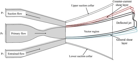
The schematic diagram of the counter-flow TVC system is sketched in Fig. 1. Curly suction collars are situated on the upper and lower sides of the convergent-divergent (C-D) nozzle. Two fixed gaps between the C-D nozzle and the suction collar are assembled to convey secondary flows. As the upward jet deflection appears, the suction flow between the vectoring jet and the upper suction collar forms because of the counter-current shear layer acting on the mix mass from surrounding fluids. The counter-flow TVC was first proposed by Strykowski and Krothapalli [19] and they expounded the possibility of utilizing a counter-flow concept to gain high vectoring performance. Alvi et al. [20,21] experimentally studied the multi-axis thrust vector nozzle of Ma = 2.0 and defined important performance parameters, involving the deflection angle and secondary mass flow ratio, respectively. Further experimental study on the counter-flow TVC of Ma = 2.0 was conducted by Flamm [22] and they stated that the thrust vectoring angle increases with the decreasing NPR. Subsequently, Hunter and Deere [23] numerically investigated a 2-D counter-flow TVC using the k-ε turbulence model and elucidated that the numerical result matches experimental data precisely. In 2015, Deng and Kim [24] numerically investigated a three-dimensional counter-flow TVC system in a circular C-D nozzle and expounded that the jet attachment appears with the decreasing suction pressure up to the critical value. Lim et al. [25] conducted experimental and computational studies on a counter-flow TVC system of Ma = 1.5 and illustrated that high thrust vector angles are obtained with less than 5% secondary flow mass flow ratio. In 2019, Wu et al. [26,27] computationally studied steady and unsteady characteristics of a 2-D counter-flow TVC system and illuminated hysteresis behaviors of key performance parameters by varying the NPR and SPR linearly. Additionally, Strykowski et al. [28] experimentally examined a supersonic mainstream of 670 K and reported that the film-cooling effectiveness is available from the suction flow between the hot primary jet and the upper suction collar.
Although many pieces of research for optimizing the performance of the counter-flow TVC system had been investigated in the last few decades, most investigations mainly focused on experimental tests and 2-D numerical simulations. The stability of the counter-flow TVC system under small values of NPR was proved previously; however, few researchers investigated the counter-flow TVC technique with a design Mach number of more than 2. Actually, the Mach number should be extended to larger values to match higher NPR levels in actual engineering applications. Furthermore, the stability of the counter-current shear layer should be specifically tested in these situations. Therefore, the present work attempts to assess the gas-dynamic characteristics of a 3-D counter-flow TVC system in a rectangular supersonic nozzle of Ma = 2.5. Performance variations are illustrated by changing the gap height of the secondary flow duct.
2. Numerical analysis
2.1 Basics of 3-D counter-flow TVC
Some assumptions are essential to establish analytical relationships, which are expressed as follows:
(1) Flow properties of the engine inlet and outlet are stable.
(2) The internal flow-field condition is stable.
(3) Fluid parameters in exit cross-sections are uniform, including the C-D nozzle exit and two secondary duct exits.
(4) The momentum of the secondary flow is omitted because its value is far less than that of the primary flow.
The equation for calculating deflection angles of counter-flow TVC is given by:
| (1) |
Where x- and y- components of engine force are Qx and Qy, respectively. Mx and My represent x- and y- components of the exit momentum. Pe means the area-weighted average static pressure of collar exit plane. G means the gap height of the secondary duct exit and H represents the height of the primary nozzle exit. L and C represent the axial length and normal height of the suction collar, severally. D is the suction collar width. The atmospheric pressure is Patm.
Moreover,
| (2) |
With respect to the flow properties of the supersonic nozzle that occurred in the counter-flow TVC system, isentropic relationships are considered herein. The static pressure and temperature of the primary flow through the supersonic nozzle of Ma = 2.5 can be calculated by Eqs. 3, 4.
| (3) |
| (4) |
Where γ and Ma are specific heat ratio and Mach number, respectively. P means the static pressure and T represents the static temperature.
The perfect gas state equation is applied to close the entire equation system, which yields
| (5) |
Thus, the mainstream velocity through the supersonic nozzle can be expressed as follow:
| (6) |
In addition,
| (7) |
Where Pl and Pu are average static pressures on lower and upper suction collars, respectively.
The average static pressure can be approximatively evaluated from Eqs. 8, 9.
| (8) |
| (9) |
Where P2c and P1c are static pressures on lower and upper suction collars, where the fluid leaves the secondary duct exits.
Hence,
| (10) |
To evaluate the thrust vectoring performance of the counter-flow TVC system, the amplification extent of thrust is indicated by the resultant thrust coefficient (Cf), which is defined by the ratio of resultant and ideal thrusts.
| (11) |
| (12) |
| (13) |
2.2 Computational procedure
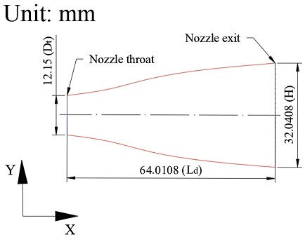
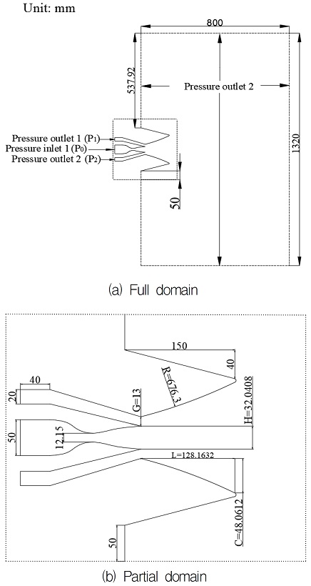
In the aspect of the convergent-divergent (C-D) nozzle, its divergent portion is designed based on the Method of Characteristics, as shown in Fig. 2. The nozzle throat radius (Rt) of 6.075 mm and the fully expanded Mach number (Ma) of 2.5 are essential to input in the software of Matlab; therefore, a smooth divergence part of the supersonic nozzle having an exit height (H) of 32.0408 mm and a length (Ld) of 64.0108 mm is obtained herein. Then, another smooth convergence part is connected with the above divergent part at the throat section. The nozzle width (D) is 40 mm. Fig. 3 presents the geometric sizes of the counter-flow TVC system in detail. To realize effective vectoring control, two ducts are necessary to place below and above the C-D nozzle. The upper duct is utilized to provide a suction flow by controlling the pressure valve. The lower duct is connected to the surrounding atmosphere. The gap height (G) of each duct is maintained at 13 mm in this section. Geometrical dimensions of the suction collar are fixed as follows: collar length L = 128.1632 mm, collar height C = 48.0612 mm, and collar radius R = 676.3 mm.
The half computational domain is made and corresponding boundary conditions are shown in Fig. 4. It extends 132Rt along the X-axis, 105Rt along the Y-axis, and 37Rt along the Z-axis to guarantee sufficient veracity. Purely structure meshes are created to improve the calculation efficiency. The dense mesh is particularly maintained at the nozzle throat, vectored region, and suction collar exit, as depicted in Fig. 4(c). The mesh density gradually decreases along positive X, Y, and Z axes after the vectored region. In addition, boundary layer meshes are created along the nozzle and collar surfaces to consider gas viscosity effects. The maximum y+ value along the collar wall is less than 0.9. Since a half domain is considered, the boundary condition of this symmetric plane is selected as the symmetry boundary. The boundary condition of the C-D nozzle inlet is set as a pressure inlet boundary. The upper suction flow duct entrance is selected as the pressure outlet boundary. The lower entrainment flow duct entrance is chosen as the pressure outlet boundary. Other exit boundaries are also chosen as the pressure outlet boundary. The total temperature is kept at 300 K. The values of SPR and NPR are set as 0.8 and 17, severally.
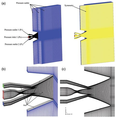
Computational mesh and boundary conditions (a) Half computational mesh and boundary conditions; (b) Partial mesh; (c) Mesh on the symmetry.
ANSYS Fluent having the density-based solver is used to calculate steady and compressible Reynolds-averaged Navier-Stokes (RANS) equations. The ideal gas is the working fluid and its viscosity is calculated utilizing Sutherland’s law. The Advection Upstream Splitting Method (AUSM) and implicit formulation are used as the solution scheme. Second-order upwind is selected to delineate the spatial discretization.
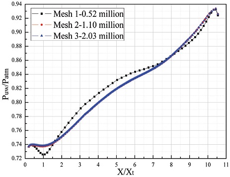
2.3 Mesh refinement analysis
The mesh refinement analysis is employed to find out the least number of elements that can offer precise numerical results. The comparison among three different computational meshes is performed that total elements are 0.52 million (Mesh 1), 1.10 million (Mesh 2), and 2.03 million (Mesh 3), respectively. Fig. 5 depicts static pressure distributions along the upper suction collar on the symmetry plane under three different refinement levels. The computational result of mesh 1 with 0.52 million nodes has some differences in comparison to another two cases. Since the node number of mesh 1 on the upper suction collar is close to half of that of mesh 2, the flow-field features in this vectored region are not captured completely. However, the pressure distributions of mesh 2 and 3 overlap one another, indicating that the flow characteristics are almost absolutely captured using mesh 2. Even though the node number continues to increase along the upper suction collar, the pressure profile does not vary significantly. Therefore, the mesh 2 of 1.10 million nodes can not only obtain adequately precise results but also save a lot of calculation time.
3. Results and discussions
3.1 Validation
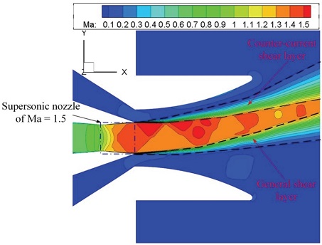
The suitability and accuracy of the present numerical methodology and turbulence model are validated against the experimental test referred to Lim et al. [25]. They experimentally examined a counter-flow TVC system in a rectangular supersonic nozzle of Ma = 1.5 for NPR = 3 and SPR = 0.8. Three static pressure transducers were installed along the centerline of the upper suction collar, linking to electronic scanning devices to collect the static pressure. Experimentally measured static pressure values are presented in Fig. 6. With regard to the current numerical validation, a rectangular supersonic nozzle of Ma = 1.5 was designed by Method of Characteristics and all dimensions of the suction collar were identical to those in the experimental test. In earlier numerical studies from Hunter and Deere [23] and Wu et al. [26], they testified that the k-ε turbulence model could capture the shear layer variations precisely. Normalized static pressure distributions based on standard k-ε and SST k-ω turbulence models are compared with experimental data, as shown in Fig. 6. It is found that the standard k-ε turbulence model gives a better match with the experimental data in comparison to the SST k-ω turbulence model. To qualitatively assess the shear layer variation, Fig. 7 depicts the Mach number contour on the symmetry plane, which is calculated by the standard k-ε turbulence model. It is seen that the counter- current and general shear layers are clearly captured in the vectored flow-field region. The counter-current shear layer significantly affects the secondary flow mass flow rate on the upper side. The secondary flow mass flow rate on the lower side is related to the entrainment effect of the mainstream. Furthermore, only one primary shock exists between the counter-current and general shear layers, where there is no strong shock interaction. Therefore, the standard k-ε turbulence model is quite suitable to reveal the flow characteristics of the counter-flow TVC system.
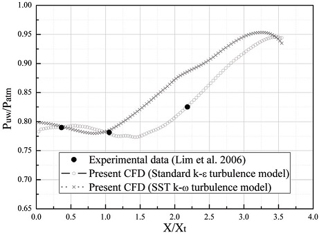
Validation of static pressure distributions along the centerline of the upper suction collar between numerical and experimental results (Ma = 1.5, NPR = 3, and SPR = 0.8).
3.2 Effect of the gap height
In this section, the performance of the counter-flow TVC system is studied at different gap heights to optimize the vectoring effect. Variations of key performance parameters are expounded herein. Static pressure distributions along the centerline of the upper suction collar at different gap heights are presented in Fig. 8. At X/Xt < 1, three different variation trends of the static pressure distribution are observed. With respect to G/H = 0.41, the static pressure is almost constant. The static pressure declines to the lowest level for the case of G/H = 0.28, whereas it continuously increases for G/H = 0.53. Beyond X/Xt = 1, static pressure distributions are found to abide by a similar tendency that it increases rapidly up to a peak value followed by a tiny decrease. Moreover, higher static pressure is obtained for a smaller gap height. Because the mainstream squeezes the secondary flow passage more seriously for a smaller gap height.
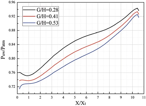
Static pressure distributions along the centerline of the upper suction collar for different gap heights.
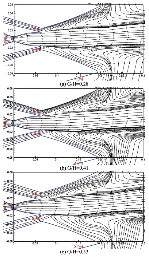
To further explain the static pressure variations, the streamlines on the symmetry plane are depicted in Fig. 9. It is found that the counter-flow is observed in the upper secondary flow passage for each case. Moreover, the counter-flow passage is affected by the size of the primary flow discharged from the supersonic nozzle. A local flow acceleration occurs in the upper counter-flow passage, resulting in an increase in the static pressure. Further, a smaller gap height causes a faster flow acceleration, leading to a larger static pressure distribution.
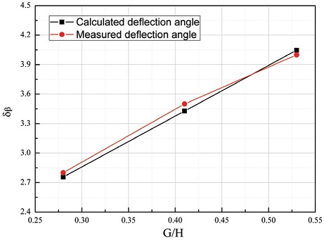
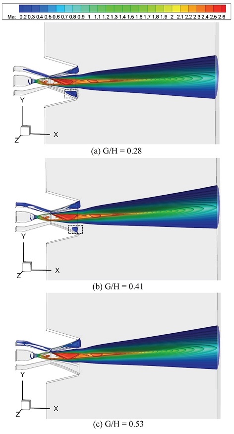
The examination of the counter-flow TVC system in the aspect of the pitching angle is performed in Fig. 10 for three different gap heights. Calculated deflection angles based on Eq. 1 are compared with measured thrust vector angles. The methodology to measure the thrust vectoring angle in the present work is referenced from Heo and Sung [12] and Heo et al. [13]. The included angle between the centerline of primary shock and the axle wire of supersonic nozzle is measured. It is found that there is an excellent agreement by comparing both methods. Further, it is found that the deflection angle increases with increasing gap height. Computational results of 3-D iso-Mach number contour for different gap heights are depicted in Fig. 11. A closer look at the entrainment flow side indicates that a relative high-velocity flow zone forms for G/H = 0.28 and 0.41, which gradually diminishes until it disappears with the increasing gap height, as exhibited in the black dotted frame. Therefore, the pressure difference between the lower and upper suction collars increases with the decay of this high-velocity flow region, which corresponds to the increase of the pitching angle.
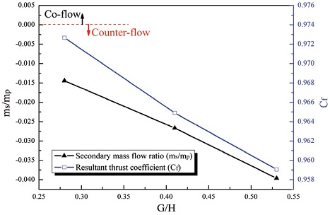
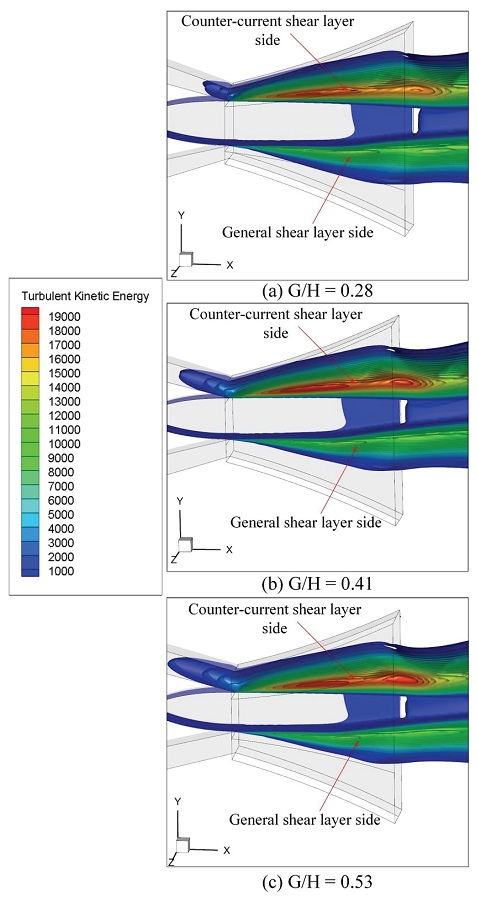
The assessment of secondary mass flow ratio, ms/mp, and resultant thrust coefficient, Cf, is presented in Fig. 12 for different gap heights. Negative and positive values of the suction mass flow ratio denote the counter-flow and co-flow respectively. It shows that counter-flows with various suction mass flow ratios are gained in all circumstances. It can be further found that the suction mass flow ratio increases with the increasing gap height. Moreover, the increasing gradient of the suction mass flow ratio is almost linear. Combined with 3-D iso-Mach number contours in Fig. 11, it is observed that the suction flow is more active for a larger gap height, where the higher flow velocity exists between the primary flow and the upper collar wall. Additionally, the resultant thrust coefficient diminishes with the increasing gap height, which is mainly affected by the decline of the realistic resultant thrust, Fr, according to Eqs. 11-13. To physically illustrate the decay of the thrust coefficient, 3-D iso-turbulent kinetic energy contours for various gap heights are depicted in Fig. 13. The turbulent kinetic energy in the general shear layer side is small in comparison to that for the counter-current shear layer side. As the gap height increases, the turbulent kinetic energy in the counter- current shear layer side remarkably enlarges, which can lead to more flow loss. The decreasing thrust coefficient is closely associated with the flow loss.
4. Conclusions
Computational studies of the counter-flow TVC system in a rectangular supersonic nozzle of Ma = 2.5 have been conducted herein. The present computational methodology using a standard k-ε turbulence model is confirmed by validating static pressure distributions along the centerline of the upper suction collar taken from the numerical simulation and experimental test. The effects of different gap heights on the performance of the counter-flow TVC are illustrated. Important conclusions are drawn as follows:
Although the reduction of the exit height of the secondary flow duct is more desirable in terms of minimizing the assembly size of the suction collar and drag reduction, the avoidance of the mainstream attachment is a prerequisite. Moreover, the larger gap height supplies a higher deflection angle. However, the suction mass flow ratio and thrust coefficient decrease with the increment of the gap height. Therefore, a suitable gap height should be especially considered in the design process of the fighter aircraft.
Nomenclature
| a : | sound velocity |
| C : | collar height |
| Cf : | resultant thrust coefficient |
| D : | nozzle and collar width |
| Fi : | ideal thrust |
| Fr : | resultant thrust |
| G : | gap height |
| H : | exit height of the supersonic nozzle |
| L : | collar length |
| Ld : | divergent part length of the supersonic nozzle |
| mp : | mass flow rate of the supersonic nozzle |
| ms : | mass flow rate of the active secondary slot |
| ms/mp : | secondary mass flow ratio |
| Ma : | Mach number |
| Mx : | x-component of the collar exit momentum |
| My : | y-component of the collar exit momentum |
| P : | static pressure |
| P0 : | stagnation pressure |
| P1 : | stagnation pressure of the upper duct inlet |
| P1c : | static pressure at the upper duct exit |
| P2 : | stagnation pressure of the lower duct inlet |
| P2c : | static pressure at the lower duct exit |
| Patm : | ambient pressure |
| Pe : | area-weighted average static pressure of the suction collar exit |
| Pl : | average static pressure on the lower suction collar |
| Pu : | average static pressure on the upper suction collar |
| Puw : | static pressure on the upper suction collar |
| Qx : | horizontal component of the aircraft force |
| Qy : | vertical component of the aircraft force |
| R : | collar radius |
| Rg : | gas constant |
| T : | temperature |
| T0 : | stagnation temperature |
| V : | flow velocity |
| Xt : | throat radius of the nozzle |
| ρ : | nozzle exit density |
| γ : | specific heat ratio |
| δβ : | deflection angle |
| NPR : | nozzle pressure ratio, NPR = P0/Patm |
| SPR : | secondary pressure ratio, SPR = P1/Patm |
Acknowledgments
[이 논문은 한국추진공학회 2019년도 춘계학술대회(2019. 5. 29-31, 라마다프라자 제주호텔) 발표논문을 심사하여 수정·보완한 것임.]
This work was supported by the National Research Foundation of Korea (NRF) grant funded by the Korea government(MSIP) (No. NRF-2016R1A2B3016436).
References
-
Francis, M.S., “Air Vehicle Management with Integrated Thrust-Vector Control,” AIAA Journal, Vol. 56, No. 16, pp. 1-11, 2018.
[https://doi.org/10.2514/1.J056768]

-
Das, S.S., Páscoa, J.C., Trancossi, M. and Dumas, A., “Computational Fluid Dynamic Study on a Novel Propulsive System: ACHEON and Its Integration with an Unmanned Aerial Vehicle (UAV),” Journal of Aerospace Engineering, Vol. 29, No. 1, pp. 04015015-1-04015015-16, 2016.
[https://doi.org/10.1061/(ASCE)AS.1943-5525.0000498]

-
Herbst, W.B., “Future Fighter Technologies,” Journal of Aircraft, Vol. 17, No. 8, pp. 561-566, 1980.
[https://doi.org/10.2514/3.44674]

- Henderson, W.P., “Propulsion System Integration in High Performance Aircraft,” Journal of Aerospace Engineering, Vol. 10, pp. 21-25, 1990.
-
Deere, K.A., “PAB3D Simulations of a Nozzle with Fluidic Injection for Yaw Thrust-Vector Control,” 34th AIAA/ASME/SAE/ASEE Joint Propulsion Conference & Exhibit, Cleveland, O.H., USA, AIAA 98-35113, Jul. 1998.
[https://doi.org/10.2514/6.1998-3254]

-
Deere, K.A., “Summary of Fluidic Thrust Vectoring Research Conducted at NASA Langley Research Center,” 21st AIAA Applied Aerodynamics Conference, Orlando, F.L., USA, AIAA 2003-3800, Jun. 2003.
[https://doi.org/10.2514/6.2003-3800]

-
Ferlauto, M. and Marsilio, R., “Numerical Simulation of Fluidic Thrust-Vectoring,” Journal of Aerospace Science, Technology and Systems, Vol. 95, No. 3, pp. 153-162, 2016.
[https://doi.org/10.1007/BF03404724]

-
Gu, R., Xu, J. and Guo, S., “Experimental and Numerical Investigations of a Bypass Dual Throat Nozzle,” Journal of Engineering for Gas Turbines and Power, Vol. 136, pp. 084501-1-084501-6, 2014.
[https://doi.org/10.1115/1.4026943]

-
Wu, K.X. and Kim, H.D., “Numerical Study on the Shock Vector Control in a Rectangular Supersonic Nozzle,” Proceeding of the Institution of Mechanical Engineers, Part G: Journal of Aerospace Engineering, Vol. 233, No. 13, pp. 4979-4987, 2019.
[https://doi.org/10.1177/0954410019834133]

-
Wu, K.X. and Kim, H.D., “Fluidic Thrust Vector Control Using Shock Wave Concept,” Journal of the Korean Society of Propulsion Engineers, Vol. 23, No. 4, pp. 10-20, 2019.
[https://doi.org/10.6108/KSPE.2019.23.4.010]

-
Deng, R.Y. and Kim H.D., “A Study on the Thrust Vector Control Using a Bypass Flow Passage,” Proceedings of the Institution of Mechanical Engineers, Part G: Journal of Aerospace Engineering, Vol. 229, No. 9, pp. 1722-1729, 2015.
[https://doi.org/10.1177/0954410014558693]

-
Heo, J.Y. and Sung, H.G., “Fluidic Thrust-Vector Control of Supersonic Jet Using Coflow Injection,” Journal of Propulsion and Power, Vol. 28, pp. 858-861, 2012.
[https://doi.org/10.2514/1.B34266]

- Heo, J.Y., Yoo, K.H., Lee, Y., Sung, H.G., Cho, S.H. and Jeon, Y.J. “Fluidic Thrust Vector Control of Supersonic Jet Using Co-Flow Injection,” 45th AIAA/ASME/SAE/ASEE Joint Propulsion Conference & Exhibit, Denver, C.O., USA, AIAA 2009-5174, Aug. 2009.
-
Song, M.J., Park, S.H. and Lee, Y., “Application of Backstep Coanda Flap for Supersonic Coflowing Fluidic Thrust-Vector Control,” AIAA Journal, Vol. 52, No. 10, pp. 2355-2359, 2014.
[https://doi.org/10.2514/1.J052971]

-
Lee, Y., Park, S.H. and Kim, Y.S., “Thrust Vectoring of Sonic Jet by Using Coanda Flap and Solenoid Valve,” AIAA Journal, Vol. 54, No. 9, 2908-2915, 2016.
[https://doi.org/10.2514/1.J054993]

- Strykowski, P.J. and Forliti, D.J., “Flow Control Applications Using Countercurrent Shear,” International Symposium on Recent Advances in Experimental Fluid Mechanics, Kanpur, India, Dec. 2000.
-
Strykowski, P.J. and Krothapalli, A., “The Countercurrent Mixing Layer: Strategies for Shear-Layer Control,” 3rd Shear Flow Conference, Orlando, F.L., AIAA paper no. 93-3260, Jul. 1993.
[https://doi.org/10.2514/6.1993-3260]

-
Strykowski, P.J., Krothapalli, A. and Jendoubi, S., “The Effect of Counterflow on the Development of Compressible Shear Layers,” Journal of Fluid Mechanics, Vol. 308, pp. 63-96, 1996
[https://doi.org/10.1017/S0022112096001395]

-
Strykowski, P.J. and Wilcoxon, R.K., “Mixing Enhancement Due to Global Oscillations in Jets with Annular Counterflow,” AIAA Journal, Vol. 31, No. 3, pp. 564-570, 1993.
[https://doi.org/10.2514/3.11366]

-
Alvi, F.S. and Strykowski, P.J., “Forward Flight Effects on Counterflow Thrust Vector Control of a Supersonic Jet,” AIAA Journal, Vol. 37, No. 2, pp. 279-281, 1998.
[https://doi.org/10.2514/2.705]

-
Alvi, F.S., Stryknowski, P.J., Krothapalli, A. and Forliti, D.J., “Vectoring Thrust in Multiaxes Using Confined Shear Layers,” Journal of Fluids Engineering, Vol. 122, No. 1, pp. 3-13, 2000.
[https://doi.org/10.1115/1.483220]

-
Flamm, J.D., “Experimental Study of a Nozzle Using Fluidic Counterflow for Thrust Vectoring,” 34th AIAA/ASME/SAE/ASEE Joint Propulsion Conference & Exhibit, Cleveland, O.H., USA, AIAA 98-3255, Aug. 1998.
[https://doi.org/10.2514/6.1998-3255]

-
Hunter, C.A. and Deere, K.A., “Computational Investigation of Fluidic Counterflow Thrust Vectoring,” 35th AIAA/ASME/SAE/ASEE Joint Propulsion Conference & Exhibit, Los Angeles, C.A., USA, AIAA 99-31384, Jun. 1999.
[https://doi.org/10.2514/6.1999-2669]

- Deng, R.Y. and Kim H.D., “A CFD Study on the Counterflow Thrust Vector Control,” Korean Society of Propulsion Engineers, Jeju, pp. 125-130, 2015.
-
Lim, C.M., Kim, H.D. and Setoguchi, T., “Studies on Thrust Vector Control Using a Fluidic Counter-Flow Concept,” 42nd AIAA/ASME/SAE/ASEE Joint Propulsion Conference & Exhibit, Sacramento, C.A., USA, AIAA 2006-5204, Jun. 2006.
[https://doi.org/10.2514/6.2006-5204]

-
Wu, K.X., Kim, H.D. and Jin, Y.Z., “Fluidic Thrust Vector Control Based on Counter-Flow Concept,” Proceedings of the Institution of Mechanical Engineers, Part G: Journal of Aerospace Engineering, Vol. 233, No. 2, pp. 1412-1422, 2018.
[https://doi.org/10.1177/0954410017752580]

-
Wu, K.X., Jin, Y.Z. and Kim, H.D., “Hysteresis Behaviors in Counter-Flow Thrust Vector Control,” Journal of Aerospace Engineering, Vol. 32, No. 4, pp. 04019041-1-04019041-9, 2019
[https://doi.org/10.1061/(ASCE)AS.1943-5525.0001027]

-
Strykowski, P.J., Krothapalli, A. and Forliti, D.J., “Counterflow Thrust Vectoring of Supersonic Jets,” AIAA Journal, Vol. 34, Vol. 11, pp. 2306-2314, 1996.
[https://doi.org/10.2514/3.13395]

